http://www.amazon.com/Audiovox-D1500A-P ... B0000AFX3X
"Switchable audio/video input and output let you use the player with your home TV or with video game consoles."
I was wondering if this would work for a portable. I have the screen seperated from the rest of the DVD player, with speakers and volume/brightness controls attatched.
http://i19.photobucket.com/albums/b180/ ... een001.jpg
What else would I have to do to it to make it portable-worthy? I'm planning on using it for a Mini SNES.
5" Audiovox portable DVD player D1500A
Moderator: Moderators
 .
.
Re: 5" Audiovox portable DVD player D1500A
I have some really nice pictures here:Radical wrote:http://www.amazon.com/Audiovox-D1500A-P ... B0000AFX3X
"Switchable audio/video input and output let you use the player with your home TV or with video game consoles."
I was wondering if this would work for a portable. I have the screen seperated from the rest of the DVD player, with speakers and volume/brightness controls attatched.
http://i19.photobucket.com/albums/b180/ ... een001.jpg
What else would I have to do to it to make it portable-worthy? I'm planning on using it for a Mini SNES.
http://forums.benheck.com/viewtopic.php ... highlight=
I have 2 of these, one I am trying to mod into a projector, and the other might be going into either a PC case or a handheld of some sort.
The link above is to an "ex50" external screen thread, but they are the same inside as the D1500A's.
If you are relatively new to modding, I would suggest going for the straightforward Composite linkup, the connections are in this photo:
http://picasaweb.google.com/nubie07/Aud ... 2591676498
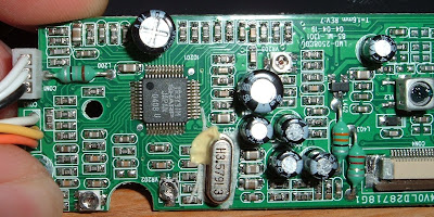
Off to the right I have soldered in my own White, Orange and Yellow wires, these are S-Video (one is ground, one color, and one intensity/brightness), if you only use Ground, and the proper connector you can connect it to Composite video easily enough. (Don't remember which, but there are only so many options, I had to fiddle a bit til I found the right ones.)
I was able to score and snap off the Backlight inverter (I had a clearly seperated High Voltage circuit, when held up to a light you could see entirely through the board in the middle, with 2-3 wires going to the Fluorescent backlight high voltage side: http://picasaweb.google.com/nubie07/Aud ... 6329595938 ), I didn't use LED backlight because this is for a DIY projector. An LED just needs enough voltage to light, and not enough to burn up. If you buy an LED it should say what the voltage is, and then you can decide on the power source. Yours seems a bit different, but might be moddable as well. EDIT: It isn't, my second D1500A has your style of power board, and I broke it trying to remove the high voltage side, now it only gives the negative voltage, no 5v+ or positive medium voltage (10-20volts). I would leave it the way it is unless someone knows something I don't. I am now using the power supply from the pictures I have, I will let you know how my LED mod goes.
I also was able to remove the brightness dial from the sound board, I didn't hook the amp back up, but it is also very easy to do. Your board seems the same as mine from what I can see. To get the amp working you just need to reconnect the ground plane, and attach the speaker wires by following the traces to the other side of the brightness control. Bonus is two headphones and a sound control!

PM me if you are still stuck, I have a really nice Macro camera (as you can see), and I can show you where to solder if you are stuck.
I don't have the book, or an SNES, so all I can show you is where to hook up stuff on the Audiovox Equipment.
These are great screens because they can take RGB input (each color has its own wire, very good color roproduction.) The irony is that Audiovox engineers didn't put it in for lack of One single wire (S-Video = 2 wires + Ground, Component[RGB] 3 wires + Ground), but the chip fully supports it and that thread has the pins to connect. It looks like very delicate soldering, and I don't know if SNES has RGB, but if your skills are up to it and the SNES does have RGB, then it is by far the best signal to hook up.
You will need 3 capacitors to hook up RGB, according to the info in that thread.
Now I am kicking myself for throwing away my Radica Sega Genesis (Mice had crapped and urinated all over it, and I thought I wouldn't want to do a handheld, now I do, and a smelly case doesn't matter, I would throw away the case). Maybe there is one on Ebay, I wanted the Red model anyway with the Sonic 2 collection.
Last edited by nubie on Fri Feb 22, 2008 10:05 pm, edited 1 time in total.
No, because component video (480/720/1080i/p) is not true Red Green Blue video signals. According to Wikipedia:ramze wrote:...does soldering the RGB inputs mean that it will accept a component cable signal, with 480i resolution?
YPbPr is converted from the RGB video signal, which is split into three components, Y, Pr and Pb.[1]
* Y carries luma (brightness) information.
* Pb carries the difference between blue and luma (B - Y).
* Pr carries the difference between red and luma (R - Y).
a green signal is not sent as the colour can be interpolated using the blue,red and luma information. This is done to save bandwidth.
http://forums.benheck.com/viewtopic.php ... highlight=
Download the PDF on the first post here, it has instructions for RGB input. Farther down the topic I post a picture of the places to connect the RGB input, it is very tight soldering, so don't attempt it without a lot of practice and a 15watt soldering iron.
To make your VGA output RGB, you need to use a utility to output 480 Interlaced. Nvidia drivers have an advanced resolution tab, or you could probably use Powerstrip for other types of video cards.
It is only a 320x240 pixel screen, so unless you want it to watch videos or monitor temperatures it probably won't work as the PC's main monitor.
If you have a videocard with "HDTV" output you can hook it to the RGB lines and then choose RGB from the video card control panel, (instead of YPrPb which is probably the default).
Download the PDF on the first post here, it has instructions for RGB input. Farther down the topic I post a picture of the places to connect the RGB input, it is very tight soldering, so don't attempt it without a lot of practice and a 15watt soldering iron.
To make your VGA output RGB, you need to use a utility to output 480 Interlaced. Nvidia drivers have an advanced resolution tab, or you could probably use Powerstrip for other types of video cards.
It is only a 320x240 pixel screen, so unless you want it to watch videos or monitor temperatures it probably won't work as the PC's main monitor.
If you have a videocard with "HDTV" output you can hook it to the RGB lines and then choose RGB from the video card control panel, (instead of YPrPb which is probably the default).