Reducing a PSone screen mobo - guide

If you're making a portable you probably need something to watch it on. (Unless you want to guess what's happening in the game, but I wouldn't advise that) Anyway, this forum is your "Hacking a pocket TV/screen" one-stop solution. Share your experiences and knowledge here.

Moderator: Moderators

bacteria
Portablizer Extraordinaire
Posts: 3984
Joined: Fri Apr 20, 2007 12:14 am
Location: Hampshire, UK
Contact:

Reducing a PSone screen mobo - guide

Post by bacteria »

Obviously, any work like this comes with the usual disclaimers - although this mod is easy to perform with reasonable soldering skills, if you don't know what you are doing you may damage your board! :roll:


I put this in my update yesterday on my IntoPlay PSone project, as this is the "portable screen hacking" forum, it is entirely appropriate to upload it here too, especially as to date there is no such step-by-step guide. The work done was all by my trusty multimeter and following the tiny traces back and forward along the board by eye.


Firstly, dremel off the pins (optional, but a good idea so you don't damage the traces by mistake when lifting off the plugs), carefully, not to harm the board.

Secondly, use pliers to gently twist off the two plugs.

Image

Then use a dremel to sand down to just under the line shown.

Image

(pic below is of my old damaged board, ignore the burnt bits)

Otherside- note, cut just short of the small holes, makes it easy to connect the headphone connections, etc.

Image

Green - rig up a wire to connect the grounds together, otherwise only one side of the board has grounding; due to removing the connecting section by the plugs. I also connected a second wire here for the battery negative connection.

Orange - solder a wire to each of the four positions - to control the screen contrast and volume settings.

Blue - the 5v line (continues to other side of board to the 7805).

Pink - 7.4v positive connection to battery.

The red line in the pic is the connection you want to solder to - I scraped the covering off to get to the trace, used flux, soldered to it and soldered wire to the connector. As the trace is slim, I used two small pieces of electrical tape to make sure only the trace was exposed when soldering the wire here, so I don't make a short.

Image

Image

Pic below is the wiring required for composite video and audio.

Blue circle is the other half of the 5v line, as above.

Image

...and the extra wiring needed for RGB:

Image

...works, and board is 7mm shorter too.

Just used a composite plug'n'play game, for this testing.

Image

As mentioned, I could easily reduce the board size further, with some extra work, but there is no point as this is as far as I need to in my project. You only need to relocate the volume and contrast contacts and a few small components, which you can cut off the board and re-wire.

Top section can be removed if using LED modded screen.

Some of the sides can be trimmed off, as it is grounding.

Using these methods, you would end up with a board about the same size as the screen itself....
Image
deviouskoopa
Posts: 144
Joined: Tue Dec 30, 2008 2:19 am
Location: Virginia Tech

Post by deviouskoopa »

Very nice... what do you mean that it's possible to shave off more of the top of the board if you LED mod the screen? (I don't really know what those components are on the top)
collinE
Posts: 891
Joined: Thu Aug 07, 2008 9:07 am
Location: Salt Lake City, Utah

Post by collinE »

This is a good guide but is pretty incomplete since it doesn't have the LED mod.

My question is if you already knew that kyo was making up a better guide to reducing the screen mobo and you had contributed to that, then why put up this one?
It takes a big man to cry, but it takes a bigger man to laugh at that man.

Ridonkulous
bacteria
Portablizer Extraordinaire
Posts: 3984
Joined: Fri Apr 20, 2007 12:14 am
Location: Hampshire, UK
Contact:

Post by bacteria »

collinE wrote:This is a good guide but is pretty incomplete since it doesn't have the LED mod.

My question is if you already knew that kyo was making up a better guide to reducing the screen mobo and you had contributed to that, then why put up this one?
I didn't contribute to Kyo's guide, my work is my own; he asked if he could use some of my work on this mod in his guide if he wanted too, I said he could if he gave me credit. I upped this mod as it was my own work and proven - why should I let him up this and take credit for my work??

As mentioned before, this wasn't designed to be a definitive guide; more of the bottom of the case can be trimmed, some of the sides too; and as you say, LED modded, and as such top too. I have no need to do this extra, but could do so; however I did need to trim the 7mm off the bottom of the board for my current project, which is what I did. I didn't need to make the mod any harder than it was.
Image
Mario
Posts: 1383
Joined: Mon Mar 05, 2007 7:20 pm
Location: Sunny California

Post by Mario »

Pretty nice. It may help me sometime. :D

Just so you know, in this picture:
Image

For the RGB and Csync connections, you could solder to the pad right below the component instead of directly to it...

Also, I see you've changed image hosts. :)
Image
bacteria
Portablizer Extraordinaire
Posts: 3984
Joined: Fri Apr 20, 2007 12:14 am
Location: Hampshire, UK
Contact:

Post by bacteria »

I use two upload services: http://tinypic.com/?t=postupload and http://imagehost.rabidusmaximus.com/ and sometimes switch between the two - TinyPic allows for larger pic sizes.

Yes, I could have soldered the RGB lines to the round contact points under the components I soldered too, however I thought for continuity I would solder to them anyway! :D

Good, hope you find it useful.

Although I mentioned it saves 7mm from the board, it actually saves more, normally you have the wires in the plugs sticking out, even if you bend them around, that takes about another 3mm on top.

Anyway, quite an easy mod to do, as long as you have a steady hand for soldering...
Image
Kyo
Senior Member
Posts: 2470
Joined: Tue Jan 02, 2007 11:59 am
Location: Germany

Post by Kyo »

My screen reduction guide will probably not be done for some time, kinda busy with school right now. It can also never hurt to hear the story from two sides, so I don't really see any reason why he shouldn't have made the guide. Fact is, mine isn't available yet. Bacteria, as how I said, if I end up using some of the information you threw out there, I'll give you credits. I'll probably give you credit either way and everyone who made an effort to help, as well as SifuF, for proving that it's possible.

I don't see how I would be "taking credit for your work", however.
bacteria
Portablizer Extraordinaire
Posts: 3984
Joined: Fri Apr 20, 2007 12:14 am
Location: Hampshire, UK
Contact:

Post by bacteria »

SifuF actually did us all a favour, it wasn't that we couldn't do board reduction, it was that no-one actually attempted it as the status quo was to leave the boards pretty well intact. When I saw what he did I thought "crikey, why didn't anyone else think of that"! He not only laid a flag in the ground but also proved it was possible. Fact is, when you think about it, the process isn't difficult. We are used to relocating and reducing controllers anyway and fairly fine soldering work!

I would have had to do what I did anyway, as my choices were either modify the molds (not ideal as I would have had a bigger and unsymmetrical case) and literally start from scratch, or reduce the board, which I would have done anyway. So technically, as of a couple of days ago, I would have been the first to do this mod out of necessity; however of course SifuF has that crown as he did it the first. Respect to him. :D He however only gave limited information on how-to and also highlighted soldering to some tiny traces rather than the end components as I did; so I had to work everything out myself with my multimeter to find out what worked with what, which took a few hours.

I would like it if SifuF did make his guide, I think it would benefit the rest of us, and may also give an alternative way to wire some of the bits up, which would be useful. Perhaps, if he gets around to it, he could also do his guide for reduction of the N64 board too??
Image
Kyo
Senior Member
Posts: 2470
Joined: Tue Jan 02, 2007 11:59 am
Location: Germany

Post by Kyo »

What SifuF did was impressive, but he wasn't the first. You talked about reducing the board before he posted his n64 and I linked you to techknotts reduction. SifuF said he'd make a guide when he has more time, but in the meantime it's up to us. I get the feeling you always see this as sort of a competition, which I really don't think it is.

That doesn't explain how I'd be "taking credit for your work", however.
bacteria
Portablizer Extraordinaire
Posts: 3984
Joined: Fri Apr 20, 2007 12:14 am
Location: Hampshire, UK
Contact:

Post by bacteria »

Actually, I phrased "taking credit for your work" incorrectly, not quite how I intended it to sound. What I meant was that collinE asked "My question is if you already knew that kyo was making up a better guide to reducing the screen mobo and you had contributed to that, then why put up this one?" which rather indicated my work being a contribution to an overall guide, which would I feel devalue as it would be a+b+c+d (with credits to a,b,c,d) presented by someone else, who would therefore be seen at taking overall credit on a sublevel, I am sure you see the point. No offense meant.

I do have a competitive spirit, but generally it is quite mild; nothing wrong with that; it helps to keep focus and strive to get better / more innovative. Look at the immense improvements my portablizing has undertaken in the last months - it is also why I went into vacuum forming, to get to "the next level" - my "competitiveness" is to be one of the best at portablizing around and make a "definitive" system or two. You don't do that with frankencasing or using perspex sheeting. However, I don't have the normal trait with competitiveness of being selfish, I want everyone to be able to replicate my work or use it to their own benefit. I share all I know with anyone who is interested.

BTW Kyo - your site looks pretty and is well presented; coming on nicely as an information source - what people have been hoping for for a while as a Wiki.

I forgot, yes, you are right, I did talk about reducing the board in my thread, however I wasn't at the stage I actually did it until recently. Talk is one thing, actions are another - so he beat me to it, all be it by a couple of weeks!

Someone said somewhere here that the L64 was the definitive N64 portable until SifuF's; however let's not forget, SifuF's was not complete - no memory card (a fair number of games need it) or rumble pack as alternative; no internal batteries and using the "C" joystick instead of buttons would be very hard in games like Banjo - imagine moving the joystick down at the same time as pressing "B" AND holding the portable in place? Also, clipping batteries onto the back, as he indicated, would really make the system thick indeed. Given that a true portable has internal batteries built-in, I suggest that, as good as SifuF's system is, it isn't definitive for those reasons. L64 still rules. Clever marketing though.
Image
Kyo
Senior Member
Posts: 2470
Joined: Tue Jan 02, 2007 11:59 am
Location: Germany

Post by Kyo »

Alright. I thought you were accusing me of secretly taking your work or something, I don't know. I'm sick, so I'm a little cranky anyway (I really shouldn't be on the PC, but everything else is boring)

I can understand where you're coming from. If I post a guide to which you contributed, it's still me who is getting the positive feedback and such (though that's really not why I'm doing it).
bacteria
Portablizer Extraordinaire
Posts: 3984
Joined: Fri Apr 20, 2007 12:14 am
Location: Hampshire, UK
Contact:

Post by bacteria »

Kyo wrote:I can understand where you're coming from. If I post a guide to which you contributed, it's still me who is getting the positive feedback and such (though that's really not why I'm doing it).
Pleased you see my point! :D
Image
Rekarp
Portablizer Extraordinaire
Posts: 2163
Joined: Thu Dec 28, 2006 1:52 am
PSN Username: Lnghrn_
Steam ID: rekarp
Location: Austin, Tx
Contact:

Post by Rekarp »

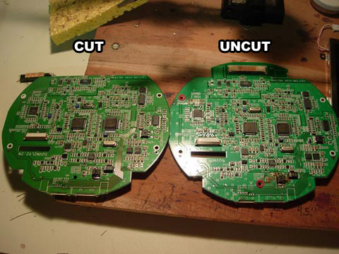
Add this picture bacteria.

Image

Thats how much more you can cut while doing the LED mod. I will search to see if I have a more up close image.

Edit// nope no such image. But you basically just cut straight along the top.

You can also cut a part off on the "left" side of the board, which is just a ground plane. This way you can get your ABXY buttons closer to the screen and thus a slightly not to wide portable.
The wood master

Image

"I was under the impression Mac owners don't actually USE their machines, they just parade them around trying to evangelize the masses."
bacteria
Portablizer Extraordinaire
Posts: 3984
Joined: Fri Apr 20, 2007 12:14 am
Location: Hampshire, UK
Contact:

Post by bacteria »

Sure, in my PSone system I use the small space above the screen for the contrast and volume buttons and the start and select ones, so wouldn't have saved any space there by removing the transformer, due to the curves of the case. Reason I had to remove part of the bottom of the screen mobo was that I couldn't reduce the top part anyway - the ribbon to the screen is short and dictates where the position of the board needs to be.
Image
deviouskoopa
Posts: 144
Joined: Tue Dec 30, 2008 2:19 am
Location: Virginia Tech

Post by deviouskoopa »

What exactly can be removed if you do the LED mod? You mentioned a transformer, is that the only component on that top part of the board?
Post Reply