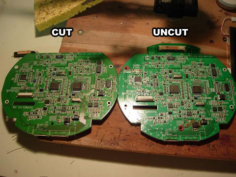
I put this in my update yesterday on my IntoPlay PSone project, as this is the "portable screen hacking" forum, it is entirely appropriate to upload it here too, especially as to date there is no such step-by-step guide. The work done was all by my trusty multimeter and following the tiny traces back and forward along the board by eye.
Firstly, dremel off the pins (optional, but a good idea so you don't damage the traces by mistake when lifting off the plugs), carefully, not to harm the board.
Secondly, use pliers to gently twist off the two plugs.

Then use a dremel to sand down to just under the line shown.

(pic below is of my old damaged board, ignore the burnt bits)
Otherside- note, cut just short of the small holes, makes it easy to connect the headphone connections, etc.

Green - rig up a wire to connect the grounds together, otherwise only one side of the board has grounding; due to removing the connecting section by the plugs. I also connected a second wire here for the battery negative connection.
Orange - solder a wire to each of the four positions - to control the screen contrast and volume settings.
Blue - the 5v line (continues to other side of board to the 7805).
Pink - 7.4v positive connection to battery.
The red line in the pic is the connection you want to solder to - I scraped the covering off to get to the trace, used flux, soldered to it and soldered wire to the connector. As the trace is slim, I used two small pieces of electrical tape to make sure only the trace was exposed when soldering the wire here, so I don't make a short.


Pic below is the wiring required for composite video and audio.
Blue circle is the other half of the 5v line, as above.

...and the extra wiring needed for RGB:

...works, and board is 7mm shorter too.
Just used a composite plug'n'play game, for this testing.

As mentioned, I could easily reduce the board size further, with some extra work, but there is no point as this is as far as I need to in my project. You only need to relocate the volume and contrast contacts and a few small components, which you can cut off the board and re-wire.
Top section can be removed if using LED modded screen.
Some of the sides can be trimmed off, as it is grounding.
Using these methods, you would end up with a board about the same size as the screen itself....