Tyromaniac's N64 Portable LOG

Includes but not limited to: SNES, Genesis, Sega CD, PlayStation 1, Nintendo 64, Dreamcast, Game Gear and I guess the Virtual Boy.

Moderator: Moderators

bacteria
Portablizer Extraordinaire
Posts: 3984
Joined: Fri Apr 20, 2007 12:14 am
Location: Hampshire, UK
Contact:

Post by bacteria »

tyromaniac wrote:
This is where I am confused....
Image
Image

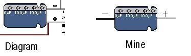
Pic of a capacitor - this is a 100uf 16v one (as you need for the TI card).

pink - the grey/light blue band indicating the wire directly under it (black arrow) is negative, other wire is therefore positive (red).
And to be even more annoying.....I'm sorry if you're pissed by now, especially you, Bacteria.
Not at all, always happy to help.
( AND ANOTHER STUPID QUESTION )Boy I really f'd up..............

I am not using a PSONE screen, so my question is: How would I deliver ground to the video pinouts as shown in the diagram.

I AM NOT GIVING UP.
Find a pinout for the screen you are using and wire the corresponding connections where they need to go. :P
Image
tyromaniac
Posts: 59
Joined: Sun Jan 06, 2008 11:29 am

Post by tyromaniac »

Well, good thing that the board has so many separate wires!
I read what you said and realized that there is probably no pin out for a portable APEX DVD screen, so I decided to see if I can figure it out on my own. and these were the results:

Image

I only plugged in a power source and when the connections in red were disconnected, the screen simply became much brighter. Therefore, I assume that the following diagram must be power.......and because it says "DANGER" written on it.

Image

I believe that the black wire is negative? which means that one of the other two must be ground......what would be a good way to decipher between which one was positive or ground?
Skyone
Moderator
Posts: 6390
Joined: Tue Nov 29, 2005 8:35 pm
Location: it is a mystery
Contact:

Post by Skyone »

Use a multimeter to measure polarity (VDC setting).
tyromaniac
Posts: 59
Joined: Sun Jan 06, 2008 11:29 am

Post by tyromaniac »

if I wired it directly to the negative power input of the screen, would that work? or does it have to go to the board first? I hope this case is true because it would be much easier. I did use a multimeter, but I got mixed readings O.o. One reading made it jump, one did nothing, and the other made the thing go backward.

This is also the decisive question in the fate of my n64:
if I can get the 3.3v light to turn on, does that mean that there's a chance it will work? I was using the multimeter with the original plug to discover that it wasn't working, so I may not have actually fried the board.
tyromaniac
Posts: 59
Joined: Sun Jan 06, 2008 11:29 am

Post by tyromaniac »

Well, I took what everyone said and decided to slow it down.....

And I used my brain O.o

Yes, I read the manual for my voltage step-down regulator to discover.....
that this is the correct setup.

Image

and if someone disagrees, please view this to help me out so I can be sure that it is correct. http://www.ti.com/lit/gpn/ptn78000w

2.2 uf capacitor should actually be 2.2k resistor O.o

My other dumb question, how does this regulator know to go to 3.3volts? is that set via the resistor?
Last edited by tyromaniac on Sat Jan 19, 2008 4:29 pm, edited 2 times in total.
Skyone
Moderator
Posts: 6390
Joined: Tue Nov 29, 2005 8:35 pm
Location: it is a mystery
Contact:

Post by Skyone »

Uh, why is that NON-POLAR capacitor a resistor?
tyromaniac
Posts: 59
Joined: Sun Jan 06, 2008 11:29 am

Post by tyromaniac »

Skyone wrote:Uh, why is that NON-POLAR capacitor a resistor?
good point..... i wasn't paying attention, will edit soon.
Good catch :P
bacteria
Portablizer Extraordinaire
Posts: 3984
Joined: Fri Apr 20, 2007 12:14 am
Location: Hampshire, UK
Contact:

Post by bacteria »

2.2uf capacitor? Shouldn't it be a 2.2k ohm resistor - that works fine!! (or a 2k ohm one). A resistor is used in Harshboy's diagram, and it is what everyone else uses...
Image
tyromaniac
Posts: 59
Joined: Sun Jan 06, 2008 11:29 am

Post by tyromaniac »

That means I need 2 2.2k resistors...as skyone and bacteria have helped me to understand.
Last edited by tyromaniac on Sat Jan 19, 2008 4:40 pm, edited 2 times in total.
Skyone
Moderator
Posts: 6390
Joined: Tue Nov 29, 2005 8:35 pm
Location: it is a mystery
Contact:

Post by Skyone »

Tyromaniac, the 2.2uF capacitor is not polarized, it's ceramic.
tyromaniac
Posts: 59
Joined: Sun Jan 06, 2008 11:29 am

Post by tyromaniac »

Image

I'm back with three more!

Yeah, wish me luck, I don't even know if they work because I broke my AC adaptor out of anger when I fried the last one.
EDIT: They work :P

and I still feel that 2600 mah isn't going to do much for my portable.
That's about an hour? Meh, that's ok......

UPDATE: I just soldered the battery and cables to the TI board and seems to be working according to my multimeter!! I'm going to test it on my Nintendo 64 soon. Wish me luck! Again!

UPDATE AGAIN AGAIN:
Wired it up to the 64, red light turns on as expected, screen flickers as normal, but then it does one of the following things:
The screen flickers red and blue...
It goes green....and stays solid.
or it just flickers.

Possible reasons: I used multimeter, everything seemed to be in working order.... but one connection was loose, resoldering after this post, and ground pin 4 was touching ground pin 1.
Would those two touching solder joints screw it up? They are ground after all??? The two same pins seemed to be connected in my last Nintendo 64 and it won't melt when I use the solder pen to it.

And possibly because there is no ground from screen to Video output.
I am testing it on a television, and I don't believe the ground from the screen is necessary just yet, but i could be wrong.
Last edited by tyromaniac on Sat Feb 09, 2008 12:02 am, edited 1 time in total.
tyromaniac
Posts: 59
Joined: Sun Jan 06, 2008 11:29 am

Post by tyromaniac »

Good news! i fried that one too :P. I really suck at this......
The Bad news is that I'm not giving up XD.

I took a look at Bacteria's instruction thread (Thank God and Bacteria for making it)....and decided that I needed to somehow make the buttons usable and not have the controller jutting out into the screen.

So I improvised, and I'm surprised that my multimeter says that it all works!!!!
B4
Image
After
Image

How it works.... Tinfoil was used to make the contacts as the original push button foam thingies from the original controller make the contacts. The jumbled mess you see will be placed on the back of my case, which I have decided to get a jump on as I wait for my secret weapon.
Image

(You are looking at the front if you haven't guessed, and the controller buttons tinfoil circuit thing will simply be placed underneath the holes on the right side of the case.
(The duct tape covers up flaws and therefore I tried to make it look almost like a design. You can see one of my flaws near the controller buttons holes.....Duct tape once again will be used as a design to cover it up and make it look better. I'm thinking a black portable with white painted duct tape or something.
Post Reply