Tyromaniac's N64 Portable LOG

Includes but not limited to: SNES, Genesis, Sega CD, PlayStation 1, Nintendo 64, Dreamcast, Game Gear and I guess the Virtual Boy.

Moderator: Moderators

tyromaniac
Posts: 59
Joined: Sun Jan 06, 2008 11:29 am

Tyromaniac's N64 Portable LOG

Post by tyromaniac »

So here I am, like I said, attempting to create something that I will ultimately end up failing in. So here I go...pictures will come at some point when I locate a camera:

I have:
My n64, a nintendo controller.......and games
I ordered and have received the voltage regulator that will power my Nintendo 64.
The battery, which was originally used for a DVD portable by APex, which is pretty crappy I must say, is a Ni-MH 7.2 volts at 2600 mA/H.
I have ordered radio shack parts that will help me solder as well as help me with the step-down regulator I ordered and now have from TI.
It will power the screen that was originally in the DVD portable itself..... but I took the screen and disconnected it from the DVD player.

The screen has a board connected that has volume control, s-video input (although it has to be in the same connector jack as an audio cable...... video input( also needs to have a audio cable connector, but I will obviously solder it to the jack), audio input,coaxial input, composite input, phone 1, and phone 2. There is also a switch in-between these inputs that changes between input and output. That's cool with me, one less thing I have to do or say I wanted to add! But I don't suggest buying this because the viewing angle is so bad that I think "video now" might have it beat.
ALTHOUGH, the viewing angle is set assuming that you are looking at an angle down toward the screen. So whenever the screen is in your lap or tilted toward your face while being played, it looks very bright and pretty good quality......for a crappy quality brand that is :P.....so I guess it will work out pretty well then!

First of all, will this battery actually power both the screen and the Nintendo 64? if so, how many minutes/hours could I possibly expect.
Or how could I do the math myself. Thank you for this awesome community!
Last edited by tyromaniac on Wed Jan 09, 2008 10:06 pm, edited 2 times in total.
HazmatB
Posts: 197
Joined: Wed Nov 28, 2007 6:23 pm

Post by HazmatB »

You would have to give us the information on power consumption of the screen before we could tell you that. If it is for a DVD player, the screen is probably 7-9 inches, which is really quite big, and will draw more power. This is especially true if it is old... However if the battery is from the DVD player, it will probably power the screen no problem, and the N64 can certainly run from those specs.

I would expect less life than the DVD player got, but not significantly.
tyromaniac
Posts: 59
Joined: Sun Jan 06, 2008 11:29 am

Post by tyromaniac »

HazmatB wrote:You would have to give us the information on power consumption of the screen before we could tell you that. If it is for a DVD player, the screen is probably 7-9 inches, which is really quite big, and will draw more power. This is especially true if it is old... However if the battery is from the DVD player, it will probably power the screen no problem, and the N64 can certainly run from those specs.

I would expect less life than the DVD player got, but not significantly.
Actually, my screen is......a mere 4.25 inches.
yeah....I got it for free if you hadn't known already. Found it in a rental car lol. The DVD player wasn't working, but the screen sure did!
Thanks for your input, time for me to open the N64 up.
kylechu
Posts: 359
Joined: Sat Feb 24, 2007 2:54 pm
Location: Everywhere and nowhere, but mostly in one place.

Post by kylechu »

Don't hurt the poor thing. It's too easy.
\
tyromaniac
Posts: 59
Joined: Sun Jan 06, 2008 11:29 am

Post by tyromaniac »

Ok then, :O I'll go easy on it.....except for the fact that after trying 8 times with the burning pen screw trick to open the darned thing......I resorted to hacksawing it open!

Pics:
http://i17.photobucket.com/albums/b74/t ... 010328.jpg
http://i17.photobucket.com/albums/b74/t ... 010327.jpg

You'll see that the lcd screen board is quite large, but oh well, I'll just throw it on top of the n64..

my next question: Is it truly necessary to add heat sinks? I'm sure after about 20 minutes it will heat up....so maybe I'll build my own heat sink out of paper clips or something...I don't know...

and my number one concern is relocating that damn cartridge port! I'll research about that cable that's supposed to relocate it later, but I couldn't stand it if that thing just stood out of the back of my portable like that.

So far so good though.
bacteria
Portablizer Extraordinaire
Posts: 3984
Joined: Fri Apr 20, 2007 12:14 am
Location: Hampshire, UK
Contact:

Post by bacteria »

Firstly don't do any modding on the fabric; and don't turn the system on - danger from static and shorting.

Yes, N64 mobo is quite big, so no issue with your screen mobo being a little large.

Yes, add heat sinks, you can make the system without but you will regret it. The metal on the N64 gets hot - try it, run your N64 for a while, then touch the metal...

Use proper heatsinks. They also have proper heat dissipating sticky stuff designed to uniform the heat from a CPU and not burn out a part (corner, etc) of the CPU. No, don't use paper clips - use proper ones. Proper heatsinks will probably cost you about £10 to cover all 3 CPU's on the N64 (see my sticky for the ones I used); you also need a quiet fan - I used an air exhaust for mine - up to you if your fan sucks air out or sucks it in.

Relocating the cart port is simple as long as you are methodical. Follow the guide in my sticky. Tip - before you remove the cart slot, mark with a felt tip CD pen a mark (eg circle) on the top left of the cart and top left of the mobo (behind where you make the mark on the cart slot) and make an "X" on the bottom right: Also mark "Front" on the front of the cart slot so you know which way round to insert the N64 cart. This way when you remove the cart slot and find somewhere to relocate it, you won't solder wires the wrong way around on the cart slot (I did this first time) - "O" to "O" and working round to "X" to "X". Logical, practical and simple!

It isn't as hard as people say to make an N64p. Be methodical and careful. Use my guide as reference, you won't regret it.
Image
tyromaniac
Posts: 59
Joined: Sun Jan 06, 2008 11:29 am

Post by tyromaniac »

Ok then. For now, I guess I won't be playing it for more than just testing......or else it will overheat and stop working.....

Today, I was happy to discover that I received all of the things I had ordered from Radioshack.com

They include:
5 2.2k resistors
2 power switches (for whatever reason)
----50 feet of 30 guage insulated wrapping wire.----
Helping Hands W/ Magnifier
an electrolytic Capacitor at 100uf
Rosin-Core Solder (with lead! My favorite)

Ok. All seems to be what I was expecting.....except that 50 feet of 30 gauge wire

I'm thinking I got the wrong kind of wire that I should be soldering with...

I've read that people have used IDE cable wire, so would that be my best bet with Nintendo 64 peripherals? Or is this incredibly thin wire actually supposed to work? The picture on the website made it look so much larger ......Oh well.
tyromaniac
Posts: 59
Joined: Sun Jan 06, 2008 11:29 am

Post by tyromaniac »

Ok. So I attempted to relocate the cartridge slot.
Turns out, relocating the cartridge slot is virtually impossible for me....
Props to anyone who has ever done it.

So...I'll be leaving where it is.
my questions remains.... is what I have spraypainted what I should follow?

I'm confused by the power diagram. Why does positive and negative come from the battery directly to the board and also from the voltage regulator???
Or is the connection from the battery directly to the board only part of the 9 volts or more extension?

http://i17.photobucket.com/albums/b74/t ... iagram.jpg

after reviewing the image, I think I do need to connect a line directly to and from the battery......contrary to what is in the image.
1. Check the power. First, make sure none of the power pins are shorted or somehow touching each other. Make sure you've got 3.3V on the 3.3V line, and at least 7.2V on the 12V line (goes to a 7805). If you don't, and you're using the original power supply, keep it unplugged for a day and then plug it in and try it. If you're still not getting power, try a new one. If you're using an alternative source of power, make sure that the 3.3V supplier can do at least 1.5A, and that the 7.2V or higher supplier can do above 100mA or so. Once you have the proper power going into the system, check that the 7805 (on the side with the chips) is outputting 5V. Turn on the system, and hope it works...
I guess that I'm wrong with my spray paint diagram then.....
tyromaniac
Posts: 59
Joined: Sun Jan 06, 2008 11:29 am

Post by tyromaniac »

So I just spent about 2 hours wiring the entire diagram....Wow...

So The screen turns on... and the system's red light turns on, and the screen starts to sort of glitch slightly when I turn it on. Is the red light a sign that it's getting the required 3.3 volts? Or what?

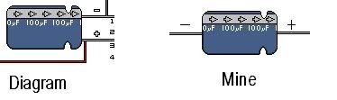
And one other question: The electrolytic capacitor: Does the side with the arrow pointing towards= positive? because that's what I have it set as.
-----( )----- my type
( ):::::::: the one in the diagram

so I don't know which side is positive or negative, but like I said, the system's red light went on.
bacteria
Portablizer Extraordinaire
Posts: 3984
Joined: Fri Apr 20, 2007 12:14 am
Location: Hampshire, UK
Contact:

Post by bacteria »

Few points here, in reply to your 3 posts: :shock:

(1) You can use the N64 without heatsinks for testing, up to a couple of minutes at a time, which is more than adequate to check all works fine.

(2) PM'ed you a reply when you PM'ed me queries about soldering technique I use.

(3) Follow my advice in my previous post about marking the cart slot prior to relocating it and the process is easy (but fiddly); you shouldn't wire things the wrong way around by this method I suggested. My thread shows step-by-step how to remove the cart slot and relocate it. It gives me a reference guide too for when I make my next one.

(4) Power diagram - don't try to reinvent the wheel, especially when you are unsure of what you are doing. You have to have the negative terminal (you didn't mark it on your pic, although it is clearly in the original pic from Harshboy) or this simply can't work. The negative terminal to the N64 mobo acts as negative for the TI card and the battery pack. Without it nothing works. Use the official wiring diagram.

(5) Having the red LED on only means it is getting power, maybe not enough amps, or maybe it is; the light only shows 3v present. Screen glitch might be if you haven't connected ground from PSone screen to the N64 mobo. It might also happen if you haven't connected the 5v line from the back of the PSone mobo to pin 12 of the larger slot (slot 1).

Don't even turn your system on without checking all the wiring is ok AND for the first time, you are getting about 3 - 3.3v output from the TI card - less that that and the system might show a red LED but won't boot, and over about 4.5v and you get smoke and fry your board. Use a multimeter.

(6) Capacitor - the light blue band with "-----" on it is the indication that it is negative, so the other side is positive. The pic is quite obvious which way around it goes.

There are a couple of different TI boards, make sure you are wiring as per the diagram for the TI board you are using - important.


You are obviously struggling this this project; so be extra careful and take lots of baby steps - if do a small bit, test it (mostly with multimeter) - especially that soldering points connect properly after you have soldered them, then next bit. Make sure after you connect wires (not to a mobo of course) that you use electrical tape to stop shorts. If you don't use this methodical method, and do lots of research on the project guides; you may as well resign yourself to frying your project as this scenario is quite likely.
Image
tyromaniac
Posts: 59
Joined: Sun Jan 06, 2008 11:29 am

Post by tyromaniac »

Ok. So I'll try and stop being a noob. :P

Meh, I think it's fried. At this moment, I can't get it to turn on. When I wire it up and plug it into the TV. Screen flickers like a normal boot up, but the " INPUT 1" does not go away, nor does anything happen obviously.

The screen still works. Which is good because I had to fix the battery which wasn't able to support the screen because I believe I left it on.

And I'm very sorry. It would seem that I have rushed this project.

Call me a noob (heck, I already know I am one), but I still don't see this light blue band on the capacitor in the picture.

This is where I am confused....
Image

so, that would be the one in the diagram, and the adjacent one would be mine. That is also how I set it up, with the positive being the one the arrow points to. Another reason it may have failed because I rushed it: the TI card I used, I soldered the wires and capacitors/resistors/etc to the long bolts pertruding under solder joints. The TI card I used also had a slight variation from the one in the picture, but as it has shown, the nintendo 64 received a steady red light when I used it.

Well, if it is fried, don't count me out yet. It has only shown me that I should take it slower when I get my hands on another one.

And to be even more annoying.....I'm sorry if you're pissed by now, especially you, Bacteria.
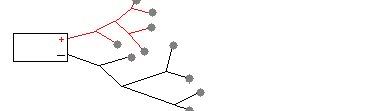
but I took my battery which I soldered two cables to, positive and negative, and continued to branch and branch from the branches.....
EXAMPLE:
Image
Which I did by directly following the path in the diagram.

( AND ANOTHER STUPID QUESTION )Boy I really f'd up..............

I am not using a PSONE screen, so my question is: How would I deliver ground to the video pinouts as shown in the diagram.

I AM NOT GIVING UP.
dragonhead
Posts: 952
Joined: Sun Apr 04, 2004 4:28 pm
Location: NH, USA

Post by dragonhead »

tyromaniac wrote: This is where I am confused....
Image

so, that would be the one in the diagram, and the adjacent one would be mine. That is also how I set it up, with the positive being the one the arrow points to.
arrows point to negative on caps
tyromaniac
Posts: 59
Joined: Sun Jan 06, 2008 11:29 am

Post by tyromaniac »

dragonhead wrote:
tyromaniac wrote: This is where I am confused....
Image

so, that would be the one in the diagram, and the adjacent one would be mine. That is also how I set it up, with the positive being the one the arrow points to.
arrows point to negative on caps
And that is how the cookie crumbles.....

THANKS I'll be sure to reverse this and hope it works.
Skyone
Moderator
Posts: 6390
Joined: Tue Nov 29, 2005 8:35 pm
Location: it is a mystery
Contact:

Post by Skyone »

I would generally think the cap would have blown up by now. :P
Gamerdude
Posts: 216
Joined: Thu Mar 01, 2007 4:37 pm
Location: Somewhere in the US

Post by Gamerdude »

Oh, thats always fun. I got a few old caps off a broken electronic device I found and threw them in the fire last time I went camping. Lots of fun!!!!!
SS64 (Super-Small N64) 8%

Gathering materials (and cash) to build it
Post Reply