Bike Smartphone Integration Project

Want to just shoot the breeze? Forum 42 is the place!

Moderator: Moderators

Post Reply
Sammybeany
Posts: 2
Joined: Thu Apr 08, 2010 7:56 am

Bike Smartphone Integration Project

Post by Sammybeany »

(I've decided to crosspost this from the Technical Questions forum, as it's been a few days since I posted it there and I haven't received any replies. Hope that doesn't bug anyone.)

After reviewing my post, I realized it's very long and a lot of people probably won't care to go through it all. So, for such people. . . .

TL;DR tech question: I need a space efficient circuit that can provide safe power to an iPhone from an intermittent power supply of either 12vAC 6w or 6vAC 3w, depending on whichever is more appropriate.

--

Anyway. Hello! I'm a long time follower of Ben and his projects. First time poster.

I've recently adopted bicycling as my primary mode of transportation. It didn't take long to realize that my iPhone could be an invaluable tool for this.

A problem I'm sure all of you smartphone owners are painfully aware of is the relatively short battery life of the average modern god phone. If I'm going to be out all day while using GPS and other functions that strain the phone, my battery will almost certainly be flat well before I'm ready to go home. There's also the problem of fumbling around with my phone in my pocket while trying to ride.

I can resolve this without too much difficulty or complexity with products already on the market:

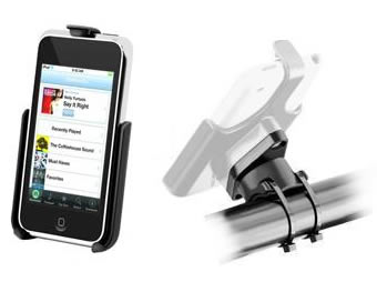
An iPhone handlebar mount can be had on eBay for about $5.
Image

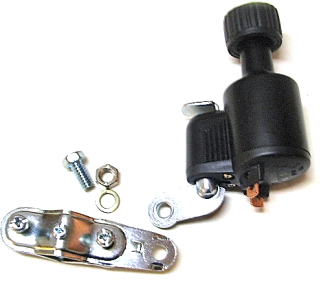
A small 12v 6w (or 6v 3w if that's more appropriate) bottle dynamo (generator) that is run by pressing a roller against a bike tire's sidewall can be had off of eBay for about $25.
Image

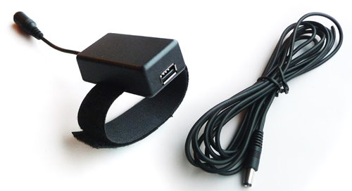
A little adapter box that takes the current generated from a dynamo and converts it to whatever is appropriate for USB devices is available, and ships out of the UK for $38.
Image

Now, none of these items are especially offensive or ugly on their own. They're all pretty utilitarian and not entirely obtrusive or bothersome. However, having a dynamo mounted on my seat stays or forks, and having a wire strung from that to a box mounted on my top tube, and then having a USB charging cable strung from that to my iPhone, then having that wire dangling from the cradle my phone is in. . . . I mean, I realize I'm never going to look as cool as the hipsters riding around on fixed gear bikes with no brakes and plastic aerospoke wheels, but I shudder to think of how dorky I'd look with this ungainly rig strung across my bike.

SO. Any suggestions of how I can do this in a more elegant way?

To be more specific, the main thing I want to ask is, what sort of voodoo magic do you suppose is going on inside that USB converter box? Here's the website for it: http://bikeusbcharger.com/" onclick="window.open(this.href);return false;

I think a tolerable solution might be figuring out a circuit that'll handle whatever it is that's going on in that box, and make it as small as possible, then attach it directly to the dynamo in an aesthetically acceptable way. As you can see, the wire that comes with it has a male/female plug set, assumedly to make the unit easier to remove from the bike. I won't be doing that. I could possibly rig up a way to make the dynamo unit itself removable, but I won't worry about that for now; I'd rather just keep it simple and clean.

I also don't need the USB port, as I'll be using this solely for my iPhone--I can pick up a dock connector from some electronics supplier and run a cable straight from the theoretical circuit on the dynamo to my phone.

The end result of this idea would be a rig consisting of the dynamo with one cable carefully and thoughtfully run from it up to the handlebars, which ends in a dock connector that hooks into the phone in the cradle. Effectively, I'd eliminate a bulky plastic box and a few stray plugs, in exchange for adding a (hopefully) small amount of bulk to the dynamo.

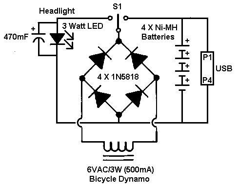
While poking around Google looking for ideas, I came across a guy who made a combination USB charger/headlight circuit powered by a dynamo. Here's his schematic:
Image

While I have a very basic understanding of what various electronic components are supposed to do, and I'm relatively handy with a soldering pen, my level of expertise with these kind of things is quite low.

From what I gather, he has a switch and a capacitor for the headlight. Those parts of the schematic would be removed for my needs, as I can't be bothered with all of that and just want this to take care of my phone. The middle part, apparently, is a bridge rectifier circuit, for the sake of providing direct current.

He has a series of batteries next in the circuit for the sake of regulating the voltage. This makes sense to me, but it's unfortunately bulky. Is it safe to assume this is what gives the converter box I linked earlier its bulk? It has also occurred to me that there's no overcharging protection in this circuit. If there's a way to eliminate the batteries, that seems best, as it would avoid any overcharging concerns and would eliminate a lot of the bulk. An obvious drawback is that I'd stop charging any time I stopped moving. I'm also wondering if I'd provide sufficient mAh to actually charge the phone, as opposed to just keeping it powered.

Well . . . I've rambled quite a bit. I'm just trying to figure things out as I go along, and typing this sort of helped! Hopefully I can figure out some good solutions and actually make this happen, and hopefully some people will offer interesting insight for the various sketchy aspects of it.

Thanks in advance!
Master Kirby
Posts: 66
Joined: Mon Aug 25, 2008 10:05 am
Contact:

Re: Bike Smartphone Integration Project

Post by Master Kirby »

I'd recommend doing some searching online for a "5v voltage regulator circuit". While I have not built one myself, I think you could use a bridge rectifier circuit, as shown in the center of the picture you posted, and remove the light, capacitor and switch.

You will want to replace the batteries that are pictured, with a large capacitor to store the energy that you generate. This should smooth out the DC signal. Instead of connecting this directly to a USB port, you may want to connect a 5 volt regulator circuit to this, and send the regulator's output to the USB port. The regulator will ensure that the output stays at 5 volts so you don't kill your iPhone by using too high a voltage.
jdmlight
Posts: 795
Joined: Thu Dec 27, 2007 11:17 pm
Steam ID: jdmlight
Location: A boring suburb of Chicago.

Re: Bike Smartphone Integration Project

Post by jdmlight »

Master Kirby wrote:I'd recommend doing some searching online for a "5v voltage regulator circuit". While I have not built one myself, I think you could use a bridge rectifier circuit, as shown in the center of the picture you posted, and remove the light, capacitor and switch.

You will want to replace the batteries that are pictured, with a large capacitor to store the energy that you generate. This should smooth out the DC signal. Instead of connecting this directly to a USB port, you may want to connect a 5 volt regulator circuit to this, and send the regulator's output to the USB port. The regulator will ensure that the output stays at 5 volts so you don't kill your iPhone by using too high a voltage.
I think Sammy should use a 12v 6w generator, and here's why. If we assume that this would use a standard linear regulator (the simple 7805, one lead is Vin, one is Vout, one is ground), 6v would be *barely* enough for the regulator to keep 5v (most regulators are happy with 6.5v+). Then we have to take into account how efficient the bridge rectifier circuit is (convert AC to DC), and I found this whilst googling:
The maximum efficiency of a Full Wave Rectifier is 81.2%.
A 6v bike generator would not produce enough voltage to use a 7805 regulator, so the 12v 6w generator is a better option. I think that a 7805 regulator is a great idea though, as Sammy probably doesn't want to accidentally fry his iPhone... I did a quick Amazon search and found this:
12v 6w bike generator
I'll draw a basic diagram and edit this post...
Edit: Here's a general idea of what to do:
Image
The diodes can be what was suggested above, 1n5818. The capacitor may not be necessary since there's a 7805 5v voltage regulator (getting rid of the capacitor would reduce the size quite a bit), also I'm unsure what size the capacitor should be - a larger uF would produce a smoother output, but it's physically bigger too. The only thing I'd caution is that since you're feeding the regulator ~12v, you need to make sure you've got a decent heatsink, otherwise you'll burn up the regulator.
--John (and please call me John, it's really weird to be called by my username)
Fight MS Paint abominations! If you don't have a camera, go here, and pick something 3 megapixels or higher.
smitty
Posts: 372
Joined: Thu Sep 24, 2009 3:45 pm
Location: the band room

Re: Bike Smartphone Integration Project

Post by smitty »

jdmlight wrote:
Master Kirby wrote:I'd recommend doing some searching online for a "5v voltage regulator circuit". While I have not built one myself, I think you could use a bridge rectifier circuit, as shown in the center of the picture you posted, and remove the light, capacitor and switch.

You will want to replace the batteries that are pictured, with a large capacitor to store the energy that you generate. This should smooth out the DC signal. Instead of connecting this directly to a USB port, you may want to connect a 5 volt regulator circuit to this, and send the regulator's output to the USB port. The regulator will ensure that the output stays at 5 volts so you don't kill your iPhone by using too high a voltage.
I think Sammy should use a 12v 6w generator, and here's why. If we assume that this would use a standard linear regulator (the simple 7805, one lead is Vin, one is Vout, one is ground), 6v would be *barely* enough for the regulator to keep 5v (most regulators are happy with 6.5v+). Then we have to take into account how efficient the bridge rectifier circuit is (convert AC to DC), and I found this whilst googling:
The maximum efficiency of a Full Wave Rectifier is 81.2%.
A 6v bike generator would not produce enough voltage to use a 7805 regulator, so the 12v 6w generator is a better option. I think that a 7805 regulator is a great idea though, as Sammy probably doesn't want to accidentally fry his iPhone... I did a quick Amazon search and found this:
12v 6w bike generator
I'll draw a basic diagram and edit this post...
Edit: Here's a general idea of what to do:
Image
The diodes can be what was suggested above, 1n5818. The capacitor may not be necessary since there's a 7805 5v voltage regulator (getting rid of the capacitor would reduce the size quite a bit), also I'm unsure what size the capacitor should be - a larger uF would produce a smoother output, but it's physically bigger too. The only thing I'd caution is that since you're feeding the regulator ~12v, you need to make sure you've got a decent heatsink, otherwise you'll burn up the regulator.
In regards to the heatsink, bikes are generally metal.... Perhaps not the best option, but definitely the least bulky.
Mario wrote:Yes, I've gone to my local Wal-Mart and was amazed at their selection of resistors, inductors, and FPGA chips. :roll:
Image
Post Reply