Reverse engineering the jumper pak

Includes but not limited to: SNES, Genesis, Sega CD, PlayStation 1, Nintendo 64, Dreamcast, Game Gear and I guess the Virtual Boy.

Moderator: Moderators

Post Reply
thewise1
Portablizer Extraordinaire
Posts: 1413
Joined: Sun Jan 04, 2009 8:18 pm
Location: Sitting on my pile of authentic minnesota dirt

Reverse engineering the jumper pak

Post by thewise1 »

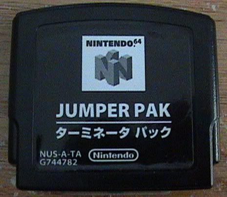
Now that it's easy to put in an expansion pak if you have the right tools by replacing the ram chips. All we have left to do is make our own jumper pak. Now lets get started.

Here is an official nintendo jumper pak, revision 3.
Image

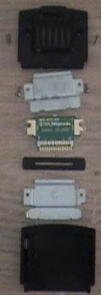
Here's it disassembled.

Image

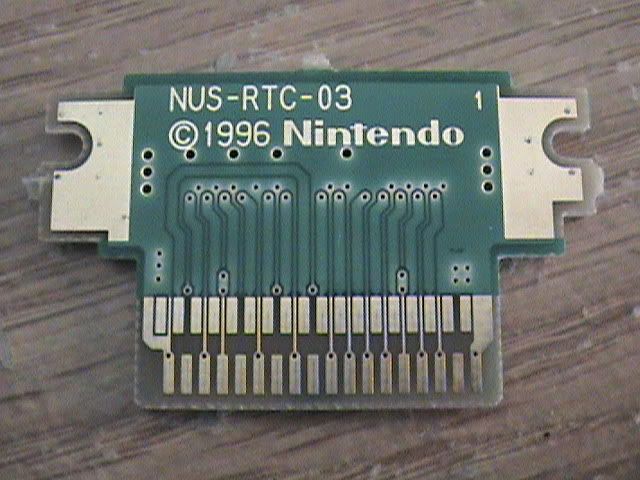
Here's the front.

Image

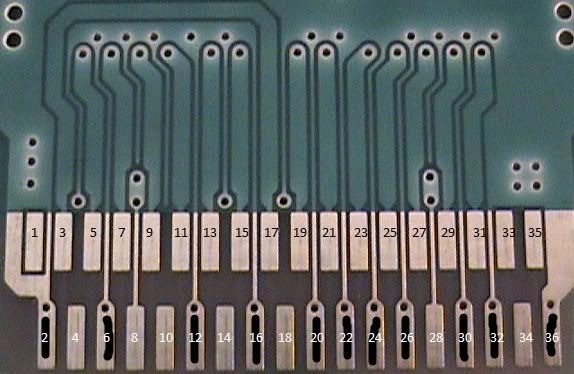
Here's a closeup of the traces. Black lines are ground.
Image

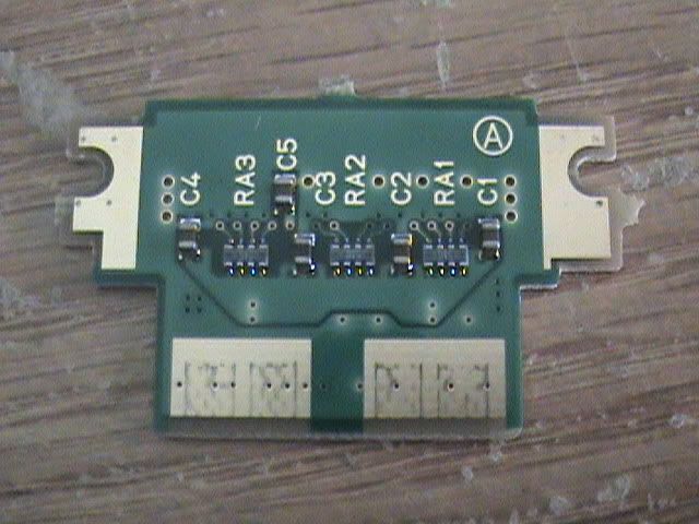
Here's the back.

Image

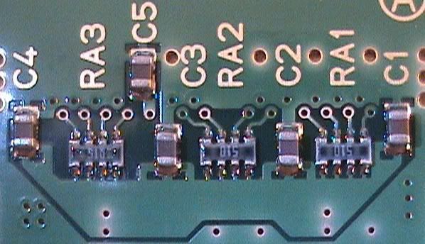
Here are the back components.

Image

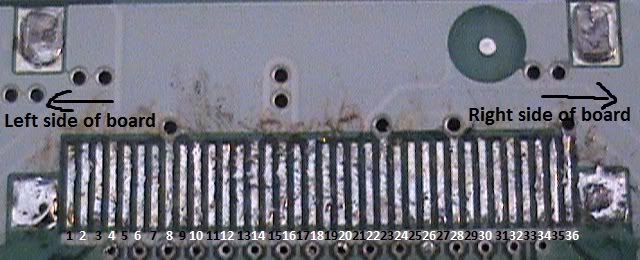
Here is a N64 without the jumper pak slot.
Image

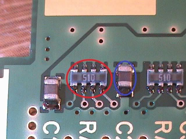
Here are the two kinds of components. Red circle is the resistor pack, each one measuring 51 ohms. Blue circle is a surface mount capacitor, 3.3 microfarads.
Image

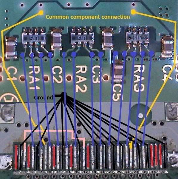
Here's the wiring diagram I made.
RED: Pins are not connected to anything
Black: pins are ground, remember to tie the ground to all the correct ends of the components
gold: common component connection between all components (except capacitor 5) and two pins
BLUE: pins connected to components
pink. two pins need to be bridged.

LATER REVISIONS OF THE JUMPER PAK DON'T HAVE THE 5TH CAPACITOR, SO PIN 23 CAN BE LEFT UNCONNECTED TO ANYTHING
Image

Here are some notes I took while doing this.

1. Copper pins pattern starts high on the left and ends low on the right.

2. 9 pins are not connected: 1, 4, 10, 14, 18, 23, 33, 34, 35

3. 11 pins are ground: 2, 6, 12, 16, 20, 22, 24, 26, 30, 32, 36

4. 2 pins are connected to eachother: 3, 17

5. 2 pins are connected to common component connection: 8, 28


What are the benefits of this?
Even if you relocate the jumper pak, a little bit still sticks out of the front of the n64. Also if the values are figured out then you can make your own jumper pak. And knowing what pins you can bridge like ground and what aren't connected are nice too. :D

Please point out any mistakes.

This has been confirmed working by several members of the forum.
Last edited by thewise1 on Tue Aug 18, 2009 10:44 am, edited 1 time in total.
ImageImageImageImageImageImage
eagle5953
Moderator
Posts: 1892
Joined: Mon Jul 07, 2008 5:06 pm
360 GamerTag: eagle5953
Steam ID: eagle5953
Contact:

Re: Reverse engineering the jumper pak

Post by eagle5953 »

I believe Skyone did this some time ago here...
Skyone
Moderator
Posts: 6390
Joined: Tue Nov 29, 2005 8:35 pm
Location: it is a mystery
Contact:

Re: Reverse engineering the jumper pak

Post by Skyone »

Yeah...and I think a few members already put it to use. It works fine.
thewise1
Portablizer Extraordinaire
Posts: 1413
Joined: Sun Jan 04, 2009 8:18 pm
Location: Sitting on my pile of authentic minnesota dirt

Re: Reverse engineering the jumper pak

Post by thewise1 »

How does a resistor array work then? When I measure two resistors on one side it gives me 102 ohms.

Well at least I can say I got pictures. :lol:

O yeah and whats the value for C5? Or does that capacitor not matter?
ImageImageImageImageImageImage
Skyone
Moderator
Posts: 6390
Joined: Tue Nov 29, 2005 8:35 pm
Location: it is a mystery
Contact:

Re: Reverse engineering the jumper pak

Post by Skyone »

My revision of the Jumper Pak doesn't have a C5. Resistor arrays are just packages of multiple resistors. Generally no fancy exceptions.
timmeh87
Senior Member
Posts: 3047
Joined: Mon Nov 14, 2005 10:19 pm
Location: Ontario, Canada

Re: Reverse engineering the jumper pak

Post by timmeh87 »

thewise1 wrote:How does a resistor array work then? When I measure two resistors on one side it gives me 102 ohms.
They are 50 ohm pull-up resistors. They all are connected to +vterm (IIRC) on one side. you are measuring two of them in series.
Image

"Linux is only free if your time is worthless"
Post Reply