Doing a bit of research online I have found an interesting notation for some power supplies, batteries, AC-DC converters, solar cells, bicycle powered DC generators, and anything else which is used to output DC. They say that something's "output is x V DC open circuit voltage and y mA short circuit current". What is all this jazz about open circuit and short circuit? Is this the same as a DC item which is rated for x V at y mA?
Here is an example from electronic goldmine:
http://www.goldmine-elec-products.com/p ... ber=G16390
Random Electronics Question
Moderator: Moderators
What the voltage reads with no load, i.e. with nothing connected to the battery.output is x V DC open circuit voltage
This is a bit odder, but I'm not used to solar cells. My guess that this is the max current that would flow if you connected both terminals together directly with no resistance (which is what a short does).y mA short circuit current
Time to learn about V-I curves
Many things like solar cells, diodes, fuel cells, etc do not have a linear voltage-current relationship. Basically what I mean by linear is that the thing in question acts like a resistor: a doubling of the voltage will result in a doubling of the current, and the same with any other factor (halving, tripling..)
This is very intuitive and nice, it makes it quite easy to learn.
A lot of fancy things however, have totally nonlinear V-I curves. Take for example a solar cell:
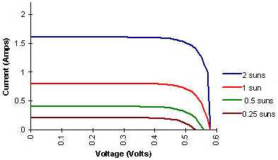
As you can see, its not linear at all (a resistor would look like a straight line with a negative slope). The implication here, at least for the solar cell, is that there is a single point where the power is at a maximum, and anywhere else you will be getting less than 100% of the available power. But Im getting off topic here.
The point is that it is impossible to communicate the entire V-I curve without drawing it, and quite often you want to put this information somewhere like on a sticker or in a line of text on a website. So instead, you are given the x and y intercept of the graph, which corresponds to short-circuit-current (voltage = 0) and open-circuit-voltage (current = 0).
This will give you a rough idea of the operating parameters, as the curve will generally slope down from left to right and you could imagine a straight line in there to approximate things (a process called linearization).
Of course, your device will never operate at either of these extremes, as the power is zero at both of them. So you will never get 1.6A out of that solar cell, nor will you see 0.58V unless it is not doing any work.
This kind of parallels how car engines are rated for power and torque, in that the numbers given are both maximums, but you cant physically realize both at the same time.
Many things like solar cells, diodes, fuel cells, etc do not have a linear voltage-current relationship. Basically what I mean by linear is that the thing in question acts like a resistor: a doubling of the voltage will result in a doubling of the current, and the same with any other factor (halving, tripling..)
This is very intuitive and nice, it makes it quite easy to learn.
A lot of fancy things however, have totally nonlinear V-I curves. Take for example a solar cell:
As you can see, its not linear at all (a resistor would look like a straight line with a negative slope). The implication here, at least for the solar cell, is that there is a single point where the power is at a maximum, and anywhere else you will be getting less than 100% of the available power. But Im getting off topic here.
The point is that it is impossible to communicate the entire V-I curve without drawing it, and quite often you want to put this information somewhere like on a sticker or in a line of text on a website. So instead, you are given the x and y intercept of the graph, which corresponds to short-circuit-current (voltage = 0) and open-circuit-voltage (current = 0).
This will give you a rough idea of the operating parameters, as the curve will generally slope down from left to right and you could imagine a straight line in there to approximate things (a process called linearization).
Of course, your device will never operate at either of these extremes, as the power is zero at both of them. So you will never get 1.6A out of that solar cell, nor will you see 0.58V unless it is not doing any work.
This kind of parallels how car engines are rated for power and torque, in that the numbers given are both maximums, but you cant physically realize both at the same time.

"Linux is only free if your time is worthless"
Very interesting. Now, I am pretty sure that the slope of that line at any given point is the negative value of the resistance of a circuit as V = I*R.
Would I be correct in assuming that those curves you showed are the negative halves of hyperbolic curves (y = 1/x) that simply have been shifted positively in both x and y directions?
Would I be correct in assuming that those curves you showed are the negative halves of hyperbolic curves (y = 1/x) that simply have been shifted positively in both x and y directions?