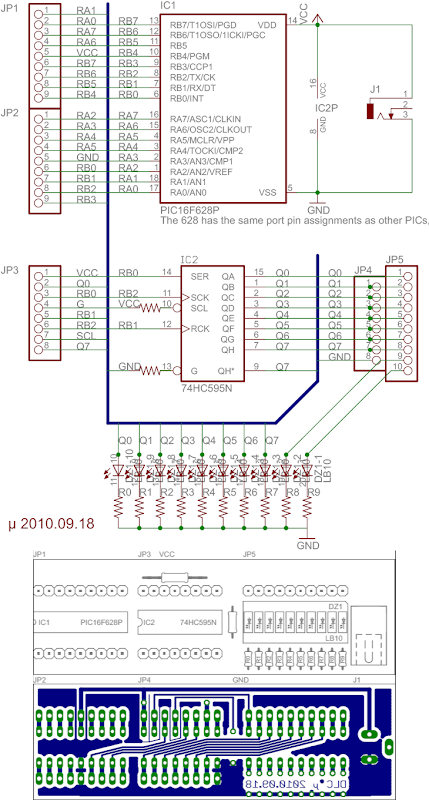
Hello everyone,
I'm trying to use a PIC 16F819 with a 74HC595 shift register, and I can't make it work. Here is the microC program:
#define dataPIN PORTB.f0
#define latchPIN PORTB.f1 //0 la tranmisie si 1 la afisare
#define clockPIN PORTB.f2 //1 dupa fiecare bit
void outOneByte(int dispData) {
int i;
clockPIN = 0; // pregatire transmitere date
for (i=0; i<8; i++) { //trimite cei 8 biti
if ((dispData & 0x01)== 1){
dataPIN = 1;}
else {dataPIN = 0;}
clockPIN =1;
clockPIN = 0;
dispData >> 1;
}
}
void main() {
int dispData, j;
TRISB = 0x00;
while(1){
for(j=0;j<255;j++){
dispData = j;
latchPIN = 0;
outOneByte(dispData);
latchPIN = 1;
delay_ms(500);
}
}
}
Is there anything wrong with it? Can anybody help? I'm quite new to this. Thank you in advance.
Best wishes!
PIC with shift register
Moderator: Moderators
Re: PIC with shift register
how exactly have you connected each pin of the 74HC595 ?
Re: PIC with shift register
Thank you for trying to help me. Here is how I connected the pins:
PINs 8 and 13 to ground
PINs 10 and 16 to +5v
PIN 14 to RB0
PIN 12 to RB1
PIN 11 to RB2
PINs 1-7 and 9 to LEDs through resistors
I also have a .1uf capacitor between PIN 12 and ground. If I take out the capacitor, all the 8 LEDs are turning on and off together. It's like I would continuously transmit 0xFF.
PINs 8 and 13 to ground
PINs 10 and 16 to +5v
PIN 14 to RB0
PIN 12 to RB1
PIN 11 to RB2
PINs 1-7 and 9 to LEDs through resistors
I also have a .1uf capacitor between PIN 12 and ground. If I take out the capacitor, all the 8 LEDs are turning on and off together. It's like I would continuously transmit 0xFF.
Re: PIC with shift register
Okay, the hardware connections are mostly correct, the capacitor is silly.
Software
edit: added english comments to code, encapsulated code in spoiler tags.
Software
- port b
TRISb (port b output enable) set- Option<7> !rbpu (port b pull up) is set?
- SPI disabled?
- Port b interrupt disabled?
- delay_ms function/macro defined?
- dispData >> 1
- >> is not an assignment operator
- did you mean to use >>=
Spoiler:
Last edited by Snow_Cat on Sat Sep 18, 2010 2:17 pm, edited 2 times in total.
Re: PIC with shift register
IT WORKS!!! 
So I didn't use the capacitor.
As for the software the mistake was ">>". That's why all the LEDs were on. I changed it to ">>=" and it works.
I didn't quite understand your questions about port B (I'm new to to this). TRISB = 0x00 sets all the pins on port B as outputs.
As for delay_ms(), this is am embeded function in microC for PIC.
I put here for reference the code that works with explanations, in case someone else is looking for a solution:
#define dataPIN PORTB.f0
#define latchPIN PORTB.f1 // 0 when transmiting and 1 for display
#define clockPIN PORTB.f2 // 1 after each bit
void outOneByte(int dispData) { // function to transmit each bit at a time
int i;
clockPIN = 0; // prepare for data transmition
for (i=0; i<8; i++) { // send 8 bits
if ((dispData & 0x01)== 1){
dataPIN = 1;}
else {dataPIN = 0;}
clockPIN =1;
clockPIN = 0;
dispData >>= 1; //here was my mistake
}
}
void main() {
int dispData, j;
TRISB = 0x00; //set port B as output
while(1){
for(j=0;j<255;j++){ //this displays numbers from 0 to 254 on 8 LEDs. As it is here bit0 is on LED8 and bit7 on LED1
dispData = j;
latchPIN = 0; //ready for transmition
outOneByte(dispData); //call the function
latchPIN = 1; //display
delay_ms(500); //pause 500ms
}
}
}
Thank you for your time and help!
So I didn't use the capacitor.
As for the software the mistake was ">>". That's why all the LEDs were on. I changed it to ">>="
and it works.I didn't quite understand your questions about port B (I'm new to to this). TRISB = 0x00 sets all the pins on port B as outputs.
As for delay_ms(), this is am embeded function in microC for PIC.
I put here for reference the code that works with explanations, in case someone else is looking for a solution:
#define dataPIN PORTB.f0
#define latchPIN PORTB.f1 // 0 when transmiting and 1 for display
#define clockPIN PORTB.f2 // 1 after each bit
void outOneByte(int dispData) { // function to transmit each bit at a time
int i;
clockPIN = 0; // prepare for data transmition
for (i=0; i<8; i++) { // send 8 bits
if ((dispData & 0x01)== 1){
dataPIN = 1;}
else {dataPIN = 0;}
clockPIN =1;
clockPIN = 0;
dispData >>= 1; //here was my mistake
}
}
void main() {
int dispData, j;
TRISB = 0x00; //set port B as output
while(1){
for(j=0;j<255;j++){ //this displays numbers from 0 to 254 on 8 LEDs. As it is here bit0 is on LED8 and bit7 on LED1
dispData = j;
latchPIN = 0; //ready for transmition
outOneByte(dispData); //call the function
latchPIN = 1; //display
delay_ms(500); //pause 500ms
}
}
}
Thank you for your time and help!
Re: PIC with shift register
I've edited the above with english comments for a more detailed explination.
Aparently the microC (IDE) you are using includes a number of functions/macros, since delay_ms(int) is not a standard function, and while I was still a lab-assistant at the institute I saw many students struggle to understand why their code suddenly stopped working with a fresh install of Keil (or was it Bloodshed?). Like other common functions, unless it is defined in the IDE's library or the user's code it will fail. And it would seem that your IDE has included it for you.
The reason that I ask about !RBPU, SPI and port B interrupt is because these other peripherials share the pins on Port B and will interfere if they are not initilized properly; which can cause otherwise perfect code to fail.
However, It would seem that your IDE has initilized them for you.
It is not entirely correct to say that the clock is high for output, and low when idle in this case. The 74HC595 is edge triggered. Meaning that the data is loaded on the rising edge of the clock pulse, and changes to the input after the propagation delay(s) are irrelevant.
The sequence for loading data through the 74HC595 is:
edit:replaced ordered list with unordered
Aparently the microC (IDE) you are using includes a number of functions/macros, since delay_ms(int) is not a standard function, and while I was still a lab-assistant at the institute I saw many students struggle to understand why their code suddenly stopped working with a fresh install of Keil (or was it Bloodshed?). Like other common functions, unless it is defined in the IDE's library or the user's code it will fail. And it would seem that your IDE has included it for you.
The reason that I ask about !RBPU, SPI and port B interrupt is because these other peripherials share the pins on Port B and will interfere if they are not initilized properly; which can cause otherwise perfect code to fail.
However, It would seem that your IDE has initilized them for you.
It is not entirely correct to say that the clock is high for output, and low when idle in this case. The 74HC595 is edge triggered. Meaning that the data is loaded on the rising edge of the clock pulse, and changes to the input after the propagation delay(s) are irrelevant.
The sequence for loading data through the 74HC595 is:
- in any order
- load shift register
- in any order
- lower shift register clock
- set next bit to load
- raise shift register clock/leading edge
- repeat until fully loaded
- in any order
- lower storage register clock
- load shift register
- raise storage register clock
- repeat until data is exausted
Spoiler: