I came across this site when i started modding xbox 360's and decided that i'd like to take a shot at the Xbox 360 LCD mod and try and put a 7" widescreen from a Digital Labs portable dvd player in the side.
I've read through the stickes on this site, as well as this site: http://www.overclock.net/case-mods-gene ... e-dvd.html" onclick="window.open(this.href);return false;
From what i've read it seems possible, but i'm just unfamiliar with the pinouts on this specific lcd. I've also read the thread from the other Digital Labs portable dvd screen and there's still a few things i'm not clear on. I've got pictures of the board if needed, but essentially there's one plug that goes to the LCD from the mainboard.
Could someone help me de-cypher??
SW = On/off switch I assume due to the switch on the mainboard which will kill the lcd screen when it's closed
+9V = Self Explanitory
GND = Self Explanitory
+5V = Self Explanitory
GND = Self Explanitory
CLK = I2C Control?
SDA = I2C Control?
NG = ?
GND = Self Explanitory
SY = S-video Intenisity?
SC = S-video Color?
INT = Something Intensity/brightness related?
SPR- = Right Speaker Negative
SPR+ = Right Speaker Positive
SPL- = Left Speaker Negative
SPL+ = Left Speaker Positive
Now, correct me if i'm wrong, but could this be used for S-Video or for connecting to an xbox or computer any way? I'm just a little shaky on the connections.
Thanks in advance!!!
Help with Pinouts
Moderator: Moderators
Re: Help with Pinouts
After researching S-Video a bit more, is there any possibility that some of those connections could be used for like a 7 pin S-Video? Just a thought..
Re: Help with Pinouts
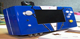
Here's a photo of the pins if this helps.

-
thewise1
- Portablizer Extraordinaire
- Posts: 1413
- Joined: Sun Jan 04, 2009 8:18 pm
- Location: Sitting on my pile of authentic minnesota dirt
Re: Help with Pinouts
S video is just composite with separate chrominance and luminance signals. If those are the signals it should be easy enough to connect an s video plug.

Re: Help with Pinouts
Thanks for the reply, it's much appreciated.
What i'm trying to find out is what these pins are, and if being not connected will throw a wrench in the plans:
INT
CLK
SDA
NG
I'm going to attempt to try to connect the SY , SC, and GND to the S-Video cable. I know the y gnd and c gnd aren't on the board, but i think i might still be able to make it work.
Any other thoughts?
Thanks very much!
What i'm trying to find out is what these pins are, and if being not connected will throw a wrench in the plans:
INT
CLK
SDA
NG
I'm going to attempt to try to connect the SY , SC, and GND to the S-Video cable. I know the y gnd and c gnd aren't on the board, but i think i might still be able to make it work.
Any other thoughts?
Thanks very much!
-
thewise1
- Portablizer Extraordinaire
- Posts: 1413
- Joined: Sun Jan 04, 2009 8:18 pm
- Location: Sitting on my pile of authentic minnesota dirt
Re: Help with Pinouts
Ground should be common throughout the system so you don't need separate grounds for s-video. As for the other 4 connections all I know is that clk stands for clock.
Re: Help with Pinouts
I appreciate it. I put a multimeter on the pins to see what I got (except the speakers cause i'm not worried about them anyway right now - Here's what I got voltage-wise:
SW = 3.36
+9V = 8.8
GND = 0
+5V = 5.05
GND = -0.01
CLK = 3.39
SDA = 3.39
NG = 4.99
GND = 0
SY = 1.0
SC = 0.63
INT = 0.02
Does this help at all?
SW = 3.36
+9V = 8.8
GND = 0
+5V = 5.05
GND = -0.01
CLK = 3.39
SDA = 3.39
NG = 4.99
GND = 0
SY = 1.0
SC = 0.63
INT = 0.02
Does this help at all?