PortaCube WIP (UPDATED: 12/20)

Includes PS2, Xbox 1, GameCube (but not the Phantom Game Console)

Moderator: Moderators

argelfraster
Posts: 984
Joined: Sun Sep 07, 2008 3:14 pm
Contact:

Re: tzt2 GCNP WIP (Portacube)

Post by argelfraster »

You don't need 14v to power the Cube.
7.4 does the job.
Image
hailrazer
Portablizer Extraordinaire
Posts: 2764
Joined: Mon Jul 10, 2006 8:57 pm
Location: Georgia Sweet Georgia

Re: tzt2 GCNP WIP (Portacube)

Post by hailrazer »

argelfraster wrote:You don't need 14v to power the Cube.
7.4 does the job.
I was told that no-one has successfully gotten it to run at under 10v. :?:

Also at 14.8v it draws a LOT less current than at 7.4v.

So 14.8v 4700mAh is going to run over twice as long as 7.4v at 4700mAh.
My Portable Systems:
Image
-----Genimini---------Darth64---------Dreamtrooper--------Ncube---------Kamikazi64---N64Boy Advance
tzt2
Posts: 54
Joined: Wed Nov 11, 2009 4:26 pm
Location: Ontario, Canada

Re: tzt2 GCNP WIP (Portacube)

Post by tzt2 »

I don't want to give the impression you can just go nuts and wire whatever DC voltage you can wire up into a piece of gear, I am not responsible for how this info is used. A good rule of thumb to follow is if you don't understand something - don't do it until you have a good understanding of what you are doing.

Any DC system can draw less current the higher the voltage, if you don't understand how this is - I would suggect looking up the old pipe analogy on voltage and current to get an idea in your head. What you have to watch out for is the tolerance of the device you are powering, go to high and poof(!) - you just fried some components in your power circuit. Mmmmm, nothing quite like burnt semiconductors! very distinct odor.

So there are tolerances, you can live inside them and be fine. Do some research on the tolerances of the item you are working with, having access to a variable, regulated power supply is a bonus, as well as having a good meter to monitor current consumption at various levels is also nice. Not everyone will have this stuff or have access to it, work within your tool set.

I also forgot to give Hailrazer thanks, the protection circuit pic I used was lifted from his how to thread, I also purchased the exact items he did for his project. So thanks man! Guess I was too pumped to be getting RE2 on my PSP (portables FTW).

I've also got a response on the material my housing is made from (!) - Cycoloy C1000, it's an ABS/PC material - so now I can go find something to make proper casing modifications, no bondo! no cracks! Will have to do some test runs on another scrap case.

edit: removing wordiness.
Last edited by tzt2 on Tue Dec 01, 2009 7:20 pm, edited 1 time in total.
tzt2
Posts: 54
Joined: Wed Nov 11, 2009 4:26 pm
Location: Ontario, Canada

Re: tzt2 GCNP WIP (Portacube)

Post by tzt2 »

Pulled apart the monitor this afternoon, sorry for the pic quality.

Here is close up of front control area of the front panel;
Image
The supporting PCB that used to live behind;
Image

The following is the connector from the pass through PCB, it connects to the rear of the above PCB, I traced the AV input through to the control board. The board this cable comes from will most likely be scrapped, no need for it.
Image

With it's protective shell removed the goomba is vulnerable...wait...what?
Image
...and here is the rear of the LCD panel itself, Toshiba built - is this the same panel in the Sony branded screens?
Image

The next step is to crack a cube open and connect this together and see what's possible to do. Most likely I will take the cube AV output back as far as I can on the PCB and tie it directly to the control board for the monitor.
Tchay
Posts: 643
Joined: Sun Apr 12, 2009 6:42 pm
Location: Hollywood

Re: tzt2 GCNP WIP (Portacube)

Post by Tchay »

looking good man! Looks like you know what you're doing! If you ever hit a road bump, feel free to PM me! Although you probably know more than I do about circuitry with your experience :lol:
Image Image
tzt2
Posts: 54
Joined: Wed Nov 11, 2009 4:26 pm
Location: Ontario, Canada

Re: tzt2 GCNP WIP (Portacube)

Post by tzt2 »

Thanks, who knows - I might need to send a PM at some point!!

Monday I cut my case for the display to sit in it, the front of the case is bowed - so I will need to fill in a gap that is fairly wide by the center of the screen. I also cut the speaker ports, instead of doing a lot of small holes I am doing stripes. Of course I'm off on my alignment, but came up with an idea to try to even the look out. The display hole is fairly square, off a little as well. Glad I'm going flat black!

Yesterday I removed the CCFL tube from the display. Soldered on leads for all 4 batteries, I used some heat shrink on the metal tabs where the joint was made to protect against shorts. The stuff I used has a sealant in it too, bonus.

Today I cut my cube controller up and 'melded' the button housing areas into my case. Now..again the curvature of the case is causing grief on a couple levels -I also mounted them in towards center as far as I could, which ended up with me having to cut away from both sides of the controller housing used and shaving c-stick plastic back (I'm afraid most will have to go on the left side for proper movement) - so with my display it causes some issues with the analog stick (left), I also mounted the controller as flush with the case as possible. After hacking away moar plastic the left side of the controller pcb sits in the case....

Man, I am happy that there is a thing as the dremel, of course I went too big in some areas! I used some MG Chemicals fast set epoxy, mixed a good amount and applied it the areas -using masking tape on the face of the case (viewing side) to let the epoxy run down and form to the flush surface. This epoxy did not list plastic as something it would bond to, but it set hard as a freaking rock. I really pressed on it to see if I could get it to pop - no deal. So the epoxy worked well for this step.

I'll get some pics up tomorrow of all this, and yeah - the cube controller is a bit of a pain. I'm almost thinking about ditching the analog shoulders (how many games really use those?) and just do the momentary switch.....I'm going to try to get them in - but it is 100% going to be a female of the dog species. I am determined to use original hardware for this. Oh, maybe I can join the hardware and housing to the rear flat portion of the case....hmmmmm

I've also decided that due to board placement and case curvature I am going to fab a PCB to move the left analog off the controller PCB, may have to either fab a PCB for the D-pad or cut that section off to use. The display panel puts the controller pcb on a bind - too much of a bind. I can screw my controller pcb down, but flexing it to squeeze *just* the lcd panel in under it puts it on enough of a bind that the analog stick no longer moves properly - let alone the stress to the board that's taking place.

So it's back to kasers thread for more details on the controller. Sorry for the boring text update today.

Have a happy Thanksgiving!
tzt2
Posts: 54
Joined: Wed Nov 11, 2009 4:26 pm
Location: Ontario, Canada

Re: tzt2 GCNP WIP (Portacube)

Post by tzt2 »

I'd like to add that after cutting and working with plastic, I have a lot of respect for what others here have done.
tzt2
Posts: 54
Joined: Wed Nov 11, 2009 4:26 pm
Location: Ontario, Canada

Re: tzt2 PortaCube WIP (UPDATED: 12/01)

Post by tzt2 »

Got a few progress pics and notes to go with them. Also have two short youtube videos of first lcd test! I think I need to ring out the selector switch i removed, the colour seems a bit off - overall it's a bit dark and I'm cool with that. My PSP stays on the lowest setting, so dim doesn't bother me, and it seems light enough actually. My perception is that the white is too...white? There were no resistors in my cube av cable, so I wired directly into the av inputs on my lcd circuitry. There used ot be a colour rotary knob, it's relocated off the board...maybe the resistance changed due to heat or wire length.

Let's take a break and look at a short video:
http://www.youtube.com/watch?v=dFI5CeerNqo

I also had issues with the audio - wide open with a very hissy, static sound. The volume control did nothing, will have to check my grounding.

Here's another short video with a better camera, still a bit out of focus:
http://www.youtube.com/watch?v=5x1YwaS-BUI

Here's a pic of the sound circuit from the sacrificial monitor, you'll note the lack of leads for the sound. I had already disconnected them. The larger interface board is going to be ditched, just haven't got that far yet.
Image


Here is a shot of the battery pack, maybe they speak Jinglish at the place the instructions were written, but I got no output out of the 'charge load' contacts. I guess I figured it was a bi directional monitoring line, guess not - had to jump off of the two sides of the pack to get power.
Image

A shot of the cube, and I'm going to be honest - this thing is going to be big. You see the four controller port pcb? yeah - all four ports are staying. Internal wavebird rx going in as well, preset to channel 1.
Image

Now, when I read the initial battery pack voltage - from warehouse to bench, uncharged - the voltage was 15.3v. I powered the cube on and thought (after about 5 minutes or so) to connect my meter up to the regulator side and plot the voltage drop over time. I have a better way to get these images, will post some of the next power draw run - maybe in a couple of days. Note that only the cube is being powered off of the batteries - I think it was on for a total of around 35-45 minutes.
Image

I had a brainfart when feeding power to the cube initially, for some reason I thought I'd just connect my voltage directly to the regulator pcb, bypassing the switch. Don't do this. I heard a pop and just like that I had blown the surface mount fuse. I clearly used safety first when applying the user approved alligator clip across the fuse. :)
Image

haha

Here are a couple shots of the case progress, it's actually farther along currently than what is shown here. Sorry for the bad shots.
Image
Image

I now have all the parts, in the next couple of days I will be wiring the internal controller, working on the shoulder triggers and a couple of other buttons I keep forgetting about - start and Z. That's the big hurdle - at the same time I'll be priming and cleaning up as much as I can in prep of first assembly.
Tchay
Posts: 643
Joined: Sun Apr 12, 2009 6:42 pm
Location: Hollywood

Re: tzt2 PortaCube WIP (UPDATED: 12/01)

Post by Tchay »

Looking great man! Oh and just FYI, your blue and green wires coming out of the power board can be soldered together. In other words, the 12v line and the 5v line can be soldered together (discovered by ShockSlayer).

EDIT: This worklog is the most professional one I have ever seen for the Gamecube!!!!! Give yourself a pat on the back!!! :mrgreen:
Last edited by Tchay on Thu Dec 03, 2009 2:27 pm, edited 1 time in total.
Image Image
andrewdorsey
Posts: 183
Joined: Mon Dec 01, 2008 2:49 pm
Location: hmmmmmmm

Re: tzt2 PortaCube WIP (UPDATED: 12/01)

Post by andrewdorsey »

:shock: wow :shock: !!!

Good work!!!
tzt2
Posts: 54
Joined: Wed Nov 11, 2009 4:26 pm
Location: Ontario, Canada

Re: tzt2 PortaCube WIP (UPDATED: 12/01)

Post by tzt2 »

Todays events were set aside for battery testing.

First chance I had this morning was to connect the cube to the battery pack and see how long they would last while only powering the cube. The batteries have NOT been charged by me to this point, and they have already run the cube for about 45 minutes or so the other day.

So, here's what I got;
Image

56 minutes to powerdown. Note on an earlier posted image where I was having to jump my power to the cube initially from the end leads for the battery pack (- & +) and not the charge load contacts on the protection circuit. Hmmm. Today I was running power out from the charge load contacts.

Ok, let's charge this stuff up now that we've drained it!;
Image

Now, I was busy working while the discharge and charge cycles were underway - so I wasn't sitting around watching this. I was using the meter to get a real good idea of what the voltage was doing. So 2 hours into charge I see the system has not rose above 12.6v, and I see this:

Image

Green light. Well, it's not charging then. So I looked at my mass of wiring and removed the ground lead from the cube that was connected to the battery pack. I must have had a bad connection with the battery charger leads - as soon as I removed the ground for the cube - the voltage spiked up to charging level at 16v~.

So the system remained in charge mode for the next 2 hours or so, I was leaving the office so I disconnected eveything and will say these batteries should be mostly charged. I may let them charge for some period of time tomorrow before I do this whole process over again - only with the display panel connected as well.

Moving on - I did a small amount of wiring today - just for the d-pad. I used a thumbtack to open the vias you see wires attached too, this allowed me to pass the wire through so I have(hopefully) a good connection on both sides. We'll see.

Image
Image

That blue wire is very small, it doesn't even have a size - it's just called 'wrapping wire' - perfect for this application. I use the shaft of my soldering iron to soften the blue insulator, then use an exacto knife (small) to fold it back from the conductor and cut it away - leaving a single strand of conductor. Any other way and you will not be very successful in stripping this wire. I got this wire from Active Electronics a few years back.

Last item today is the tools I used to open my cube, sorry for the late posting on this. I used a standard 4mm hex nut driver to remove those bottom housing screws and the standard small flathead to remove the tri-wing screws. The tri-wings needed a bit more pressure, the nut driver was the same. All removed screws are in perfect condition, perfect for the trash.

Image

That's enough for today. Next up is to continue wiring the controller boards, and wire up my 7808 to feed the display as well.....I should work more on the case as well. One day at a time though.
andrewdorsey
Posts: 183
Joined: Mon Dec 01, 2008 2:49 pm
Location: hmmmmmmm

Re: tzt2 PortaCube WIP (UPDATED: 12/03)

Post by andrewdorsey »

Wonderful!!! :D
tzt2
Posts: 54
Joined: Wed Nov 11, 2009 4:26 pm
Location: Ontario, Canada

Re: tzt2 PortaCube WIP (UPDATED: 12/03)

Post by tzt2 »

Today events. Connected battery pack to charger - pack charged for an additional 2 hours or so on top of yesterdays charge time. So we had a full charge to play with.

I wired my 7808 in to power my InterAct Mobile Monitor off of 8v, so whole system was running off the batteries. Soul Calibur 2 was still in the drive, so it mostly just was in the loop mode.....although I will admit to fighting a few matches. :)

2.5 hours of run time, here's the screengrab, note the drop off to zero volts - this is the protection circuit for the battery pack shutting off...or opening the line to prevent over discharge, start voltage was 16v:
Image

At some point while this was going on I wired the ABXY leads leaving the controller pcb, I still have to wire that external board for the abxy buttons. Here's some pics of the process, if anyone has anything to add to this, please do. And remember, it must be a sharp tip, you don't want to use blunt or chipped tips.
Image
Image
Image
Image
Image

Hope to first assemble unit end of next week, hopefully.

EDIT: I tagged each of those blue leads as they were wired, one at a time. The last thing you want to have happen is a mis-wired button!! So each end of each wire has a small piece of masking tape with the button they are, A B X or Y.
Last edited by tzt2 on Fri Dec 04, 2009 8:58 pm, edited 1 time in total.
tzt2
Posts: 54
Joined: Wed Nov 11, 2009 4:26 pm
Location: Ontario, Canada

Re: tzt2 PortaCube WIP (UPDATED: 12/03)

Post by tzt2 »

Raizer04 wrote:That was the same battery i was thinking about...that joker looks thin as heck....Good job on everything so far!
Thanks, they are pretty slim battery packs. They have a nice weight to them as well - not in the bad way. Get the appropriate protection circuit and charger for the voltage you use on your system, while mine seemed a little glitchy at first, today everything worked properly - seeing the circuit kick on to cut off the output to prevent over discharge is nice because you know it is working. Also we can see you get a solid two hours of holding a charge. The voltage really begins to bottom out in the 2hr15 - 2hr25 time frame.
tzt2
Posts: 54
Joined: Wed Nov 11, 2009 4:26 pm
Location: Ontario, Canada

Re: tzt2 PortaCube WIP (UPDATED: 12/04)

Post by tzt2 »

Was able to work on the monolith today while the wife and her brother were having some quality time with their mom. It was pretty productive as the mass onslaught of images is about to reveal. Yesterday I did a few things as well. It seems I might be doing a first assembly this week! Still have to sort out what I'm doing with the memory card. Hate to say it, mostly because I kinda want to have all of my old saves on one transferable card, but I'm not sure if I can pull off a good looking slot. Maybe - I'm going to try anyway, but it is going to have one internal memory card.

Still have to wire my Start, Z and shoulder buttons. To be honest -I hate those shoulder buttons. It's going to be nice when I don't have to dread them anymore.

First, here's something I tried yesterday and found works really well - line the edges of the display with black electrical tape to pretty much eliminate any light leakage around the edges. One layer of tape was used for each edge.
Image

Getting back to the ABXY buttons..
Image
Image
Image
Image

Filled in some gaping holes in the case, we'll have to see how it stands up to a stress test. This is the 'small' hole I have to fill. :lol:
Image
Image
Image

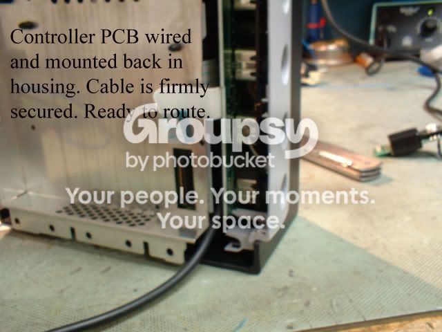
I had been concerned I might have issues running the cables to tie into the rear of the controller input pcb, today I made that connection up and am pretty happy with the results. On the bare end of this wire I am going to split off for two internal options; the internal controller or the wavebird receiver. These two items will be on a switch.
Image
Image
Image
Image
Image

Have to get started on wiring my switch-plate, there will be a few switches on the bottom of this, just as every monolith portable should have.
Post Reply