Almost done

Includes but not limited to: SNES, Genesis, Sega CD, PlayStation 1, Nintendo 64, Dreamcast, Game Gear and I guess the Virtual Boy.

Moderator: Moderators

Post Reply
_Ivan_
Posts: 20
Joined: Fri Nov 28, 2008 5:55 pm
Location: Florida, with the humidity and stuff.

Almost done

Post by _Ivan_ »

I have a fair amount of questions that need answering if I'm to finish my N64 soon. Any help is appreciated.

1.) Currently, my N64 controller is cut into three parts and I'm in the process of wiring them together. I've used a technique fairly successfully so far that involves drilling holes in the board and sticking the wires through, but I still have a hard time getting the solder to stick to the board. Pictures are encouraged.

2.) While on the topic of N64 controllers, why does the joystick have six cables? I would assume it would have five: up, down, left, right, and ground, but I've been wrong more than I have been right when it comes to this stuff. :roll: (I'm using the official controller, by the way.)


Whoops, I've got to go to school now, I'll finish he rest of this post later. :)
argelfraster
Posts: 984
Joined: Sun Sep 07, 2008 3:14 pm
Contact:

Re: Almost done

Post by argelfraster »

1) You want to dremel that that thin layer of whatever it is that is covering the trace you want to solder onto. Also use flux.

2) Joystick is up, down, left, right and two grounds.
joeyjoe9876
Posts: 604
Joined: Fri Jul 31, 2009 7:48 pm
Location: Virginia
Contact:

Re: Almost done

Post by joeyjoe9876 »

1) use an exacto knife and scrape away a bit, safer then using the dremel
My For Sale/Trade thread
N64p Coming Soon :D
_Ivan_
Posts: 20
Joined: Fri Nov 28, 2008 5:55 pm
Location: Florida, with the humidity and stuff.

Re: Almost done

Post by _Ivan_ »

I've scrapped away to the copper part, but the solder still won't stick, and I'm afraid to scrape any deeper.

Anyway, here are the rest of my questions.

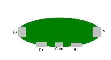
1. I've wired up the batteries to the protection circuit in what I assume is the correct way, but I'm not getting power.
Image
Batteries go to B+, B-, and Com; P+ and P- goto the PH8008080808whatever.
Anyway, when I check the power on my multimeter, B+ to B- gets ~7.4; B+ or B- to Com gets ~3.7; P+ to P- gets nothing (and any variation of B to P gets around 1-3 and quickly returns to 0). I don't think that that's normal at all and I don't know what the problem is. Is is possible that my protection circuit is faulty or broken?

2. I've been following this diagram for my wiring:
http://forums.benheck.com/viewtopic.php?f=5&t=14556
a. Where on this would I include the power switch?
b. What gauge wire should I use for the whole thing? I'm using a fair size (I'd estimate it to be ~16-20), but the wires that come with the PSOne screen are really tiny. Will that small size suffice for powering the screen?
c. Finally, my PH80800008080thing has only three leads on the left side and the one in the diagram has four. Did I order the wrong part? I can probably get the model number of mine if needed.
argelfraster
Posts: 984
Joined: Sun Sep 07, 2008 3:14 pm
Contact:

Re: Almost done

Post by argelfraster »

2)
a. Usually people put a power switch on the negative line between the console and the battery. This means that you will have to connect you Psone screen to the console for power.
b. What you are using now should be fine.
c. I think you got the PTH08080WAZ, this regulator is fine, there is just a different diagram that shows you how to connect it (which I can't find)
snowpenguin
Posts: 1306
Joined: Thu Jun 11, 2009 4:10 pm

Re: Almost done

Post by snowpenguin »

Get some flux to solder to the traces better, it de-oxidizes the contacts so that the solder sticks better.

There are separate diagrams for the PTH08000 and PTH08080.
Image
Post Reply