Do you have a technical question that doesn't really fit a specific console? Want some general info on electronics, hacking, making cookies, etc? Here's the place to ask! Go nuts.
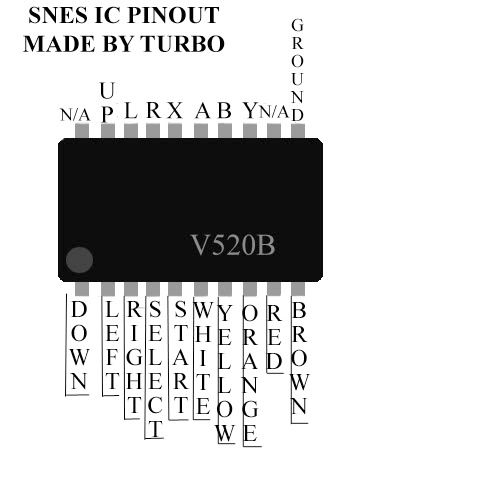
This link has information on the pinouts for which color is which pin.... I'm not really sure i understand your question...
Thnx for ur help m8. I just have one more question. I put a whole on my portable and choped my snes controller put everything back together, but I accidentaly glued the controller up side down. Here a pic.
as us can see on my picture, the down button will be set to right, and the right trigger will be set to down and so on. I was wondering if I soldered them to set down to down and right to right, will it cause any problem? Thnx
This link has information on the pinouts for which color is which pin.... I'm not really sure i understand your question...
Thnx for ur help m8. I just have one more question. I put a whole on my portable and choped my snes controller put everything back together, but I accidentaly glued the controller up side down. Here a pic.
as us can see on my picture, the down button will be set to right, and the right trigger will be set to down and so on. I was wondering if I soldered them to set down to down and right to right, will it cause any problem? Thnx
You need to wire up to the one that would be what you would want to hit for up. So you should probably wire it this way
Down you should wire as Left
Right you should wire as Down
Left you should wire as Up
Up you should wire as Right
Also, You could wire tact switches straight to the IC instead of using the controller, that might be easier for you.
Yo man, this diagram is wrong. U can take a look at my IC which I posted a pic and the diagram u posted. I dosent make any sense. theres no ground on my chip as ur diagram shows ... Any help?
What do you mean? Do you mean like you can't find where to wire to the green board the IC is on? You can wire straight to the little silver posts coming from the IC...
ok I soldered everyting p and I cant get it to work.... Any idea? I already we wiredit like 3 times, and still I cant get it to work.... Im so fustrated! Any one knows what wrong? There are no wires touching, and is all the same as the diagram.
OK nvm... Got it to work... This is how I did it. I scraped that black paint off the board and cleaned it with alcohol, then I drilled a whole just beside the exposed wire, and soldered there. Now is working! I sent pic to Kurt and he could'nt find the problem. Thnx all for your help!