Ya have to remove more than the stick, ya need to remove the circuitry that's after it as well, the Op-Amp and biasing Resistors, so you can get to just the input lead of the MCU of the controller, after that you just use that lead there as your Input for the POT (Wiper) and use the Voltage and Ground that the original stick did. That's how the older controllers work (, it's just a voltage divider - Voltage, Wiper, Ground) and is essentially how these newer sticks work, it's just a more advanced way of doing it is all, but when you trace it all out it works the exact same way. If ya plan to use the PIC/DAC setup then that X-Axis Input pin of the MCU will go to the DAC Output.
Those 2 10k Resistor in the picture there are to keep the Y-Axis of the stick centered, since I had to remove the Op-Amp and such from that side there's nothing to keep that pin of the MCU from floating and that can cause all kinds of weirdo issues.
It really depends on the version of controller as to what all and where all you'll have to remove things, I'd have to know the MSU number of the one ya were working on, but if it's one of the newer version ones you'll be pulling the one stick as well as it's Op-Amp and around 10 Resistors off the board. On the other side ya can leave it as-is or remove just the stick to save some room, no Resistors or anything need to be added/removed, just the stick it ya want.
The PIC and DAC used are mentioned in the previous post, and as soon as we have all the little things sorted the .hex will be released as well, but it'll only be good for the 16F690 that we used here. DACs are pricey, and since that one is an Octal it costs around $12, which is more than what an average Single or Dual 10bit DAC would. You can really use any 10bit DAC, so long as it has a vRef input, but it's hard to tell if there will be some 'quirk' with it until ya actually get it in circuit and see what it does, they don't all have the same specs, so substituting one for another can sometimes cause issues.
I don't have anything made up diagram wise, except scribblings on graph paper and the mess in my head, but it's POT to PIC to DAC to controller for the Twist how I have it done up right now. You'll need to isolate the lines in the neGcon, or just remove the ones on that POT and wire up 3 new ones, same goes for the Start button since it uses a different Com line than the D-pad, as well one side of the L button needs to be isolated since it's wired up backwards on the board from how ya need it to be. I stripped all the parts off the neGcon board, has to be done so those components on there don't cause issues, as well it leaves the board in there so ya have the D-pad contacts and such all in place.
PS3 Negcon Controller help pls
Moderator: Moderators
Re: PS3 Negcon Controller help pls
Screwing up is one of the best learning tools, so long as the only thing you're not learning is how to screw up.
Re-mappable Wireless 360 Controller - The CGnome
Re-mappable Wireless 360 Controller - The CGnome
-
Djdavies83
- Posts: 6
- Joined: Sun Apr 19, 2009 8:01 pm
- PSN Username: djdavies83
- Location: manchester UK
- Contact:
Re: PS3 Negcon Controller help pls
An adaptor box would be ace but I can imagin the cost.
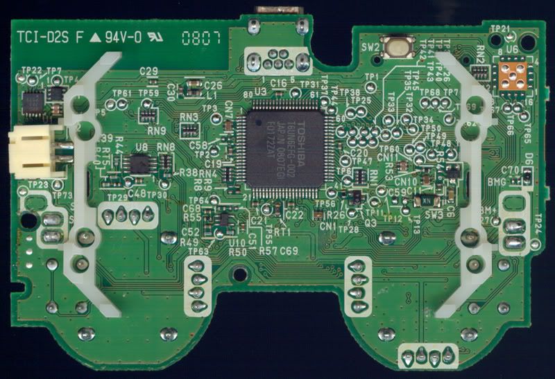
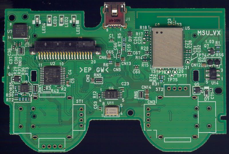
ok, I'm back in manchester and had the controller out, its a MSU_VX
Bottom
Top
Hope you don't mind me using the images from your ps pad versions page, I dont have my data cable with me to take my images out of the n95.
would you mind showing me what it is I need to remove, how to remove parts and where my negcon cables go?
Thanks again DUDE!
ok, I'm back in manchester and had the controller out, its a MSU_VX
Bottom
Top
Hope you don't mind me using the images from your ps pad versions page, I dont have my data cable with me to take my images out of the n95.
would you mind showing me what it is I need to remove, how to remove parts and where my negcon cables go?
Thanks again DUDE!
A wise man learns from his mistakes,
A wiser man learns from the mistakes of others!
A wiser man learns from the mistakes of others!
Re: PS3 Negcon Controller help pls
The cost of making the adapter wouldn't be bad $$ wise, minus the few specific tools you'd need, it's the time spent on it that would be the kicker.
You'll need to remove..
The sticks (naturally), just a soldering iron and solder sucker there, flow some new solder on those joints and crank the heat up on your iron if it has it, they can be a PITA to get all cleaned out sometimes, though it doesn't really matter if ya tear out the Vias there as ya aren't going back to stock, but it's best not to. Then you'll need to remove the mess for the Left Stick, U9 as well as pretty much every Resistor around it, RT2, RT3, R29, R30, R35, R36, R37, R43 and RN7, and for that I use a hot air rework setup, but you can remove them all by just drowning them in solder and 'wiping' them off the board, just make sure ya don't leave any shorts behind.
Then ya need to 'center' the Y axis, since ya pulled the mess that was keeping it centered and it's not going to be used anyway, plsu ya don't want it floating because that can cause issues. That means ya need a couple of 10k Resistors, both will get soldered to TP28, then one goes to Ground, the other to the Sticks 2.8v source, both spots can be used from right where the stick was installed and the Voltage is right next to the Ground spot, pic of that in the PS3 thread also, and if ya can't tell which one is Ground ya probably shouldn't be doing this.
After that it depends on which way you're going with it. TP27 is your X-Axis Input to the MCU, so if ya plan to just wire up the neGcon POT right to it then ya run the Wiper to TP27 and make sure the POT is using the Sticks Ground and Voltage spots for the outside leads, so you achieve the same voltage division as the original setup. Then it's basically the exact same thing as all that mess ya just removed, a voltage divider done with a POT instead of a Hall sensor and Op-Amp, like it was before they swapped over to this new (old by DC controller comparison though) setup. If ya plan to go the PIC/DAC route TP27 is still your X-Axis Input, just the DAC output goes to it instead.
You'll need to remove..
The sticks (naturally), just a soldering iron and solder sucker there, flow some new solder on those joints and crank the heat up on your iron if it has it, they can be a PITA to get all cleaned out sometimes, though it doesn't really matter if ya tear out the Vias there as ya aren't going back to stock, but it's best not to. Then you'll need to remove the mess for the Left Stick, U9 as well as pretty much every Resistor around it, RT2, RT3, R29, R30, R35, R36, R37, R43 and RN7, and for that I use a hot air rework setup, but you can remove them all by just drowning them in solder and 'wiping' them off the board, just make sure ya don't leave any shorts behind.
Then ya need to 'center' the Y axis, since ya pulled the mess that was keeping it centered and it's not going to be used anyway, plsu ya don't want it floating because that can cause issues. That means ya need a couple of 10k Resistors, both will get soldered to TP28, then one goes to Ground, the other to the Sticks 2.8v source, both spots can be used from right where the stick was installed and the Voltage is right next to the Ground spot, pic of that in the PS3 thread also, and if ya can't tell which one is Ground ya probably shouldn't be doing this.
After that it depends on which way you're going with it. TP27 is your X-Axis Input to the MCU, so if ya plan to just wire up the neGcon POT right to it then ya run the Wiper to TP27 and make sure the POT is using the Sticks Ground and Voltage spots for the outside leads, so you achieve the same voltage division as the original setup. Then it's basically the exact same thing as all that mess ya just removed, a voltage divider done with a POT instead of a Hall sensor and Op-Amp, like it was before they swapped over to this new (old by DC controller comparison though) setup. If ya plan to go the PIC/DAC route TP27 is still your X-Axis Input, just the DAC output goes to it instead.
Last edited by RDC on Mon Jun 29, 2009 10:53 am, edited 1 time in total.
Screwing up is one of the best learning tools, so long as the only thing you're not learning is how to screw up.
Re-mappable Wireless 360 Controller - The CGnome
Re-mappable Wireless 360 Controller - The CGnome
-
Djdavies83
- Posts: 6
- Joined: Sun Apr 19, 2009 8:01 pm
- PSN Username: djdavies83
- Location: manchester UK
- Contact:
Re: PS3 Negcon Controller help pls
Hello, would you mind taking a look at a digital mock up of what you say I should do?
I've done this because I only have one ds3 that can be used for this, I don't want to mess up
ok, so, the parts I think you said to remove are covered in yellow...

And this is of the parts to add

This probably took longer than it would have done to do the real thing but this way I can just ctrl+z my errors, I'll know the correct polarity of the neGcon pot once its on there for real.
I was clearing out my storage the other day and found a perfect project box, now it feels like im getting somewhere!
Hopefully I'll have mine up and running in the next week or two.
Thanks for your quick replies RDC
P.S. nice work on the 360 in a ds3 shell, Only found out it was you who did it a couple of days ago.
I've done this because I only have one ds3 that can be used for this, I don't want to mess up
ok, so, the parts I think you said to remove are covered in yellow...
And this is of the parts to add
This probably took longer than it would have done to do the real thing but this way I can just ctrl+z my errors, I'll know the correct polarity of the neGcon pot once its on there for real.
I was clearing out my storage the other day and found a perfect project box, now it feels like im getting somewhere!
Hopefully I'll have mine up and running in the next week or two.
Thanks for your quick replies RDC
P.S. nice work on the 360 in a ds3 shell, Only found out it was you who did it a couple of days ago.
A wise man learns from his mistakes,
A wiser man learns from the mistakes of others!
A wiser man learns from the mistakes of others!
Re: PS3 Negcon Controller help pls
Thanks, but the 3PS60 isn't the only other controller I've done.
Ya didn't mark RN7, and I forgot to add R37 and R43 that should go also. Every Resistor right around U9 there should go, that is every Resistor under where U9 is written (including U9) and to the left of where RN7 is written. You can loose the Capacitor (C47) there as well, it's not going to hurt anything if it's gone.
The rest is right, but ya may have the Red/Black wires from the neGcon POT backwards, you'll have to wire it up and see if the left/right twisting is correct, if it's backwards just swap the Red/Black wires how ya have them on the PS3 controller and then you'll be good to go. I didn't pay a bit of attention when I did mine and wired it up right the first time, and if it's inverted just swapping the wires will fix it, so if ya get it wrong it's no biggie at all and isn't gonna hurt anything.
Ya didn't mark RN7, and I forgot to add R37 and R43 that should go also. Every Resistor right around U9 there should go, that is every Resistor under where U9 is written (including U9) and to the left of where RN7 is written. You can loose the Capacitor (C47) there as well, it's not going to hurt anything if it's gone.
The rest is right, but ya may have the Red/Black wires from the neGcon POT backwards, you'll have to wire it up and see if the left/right twisting is correct, if it's backwards just swap the Red/Black wires how ya have them on the PS3 controller and then you'll be good to go. I didn't pay a bit of attention when I did mine and wired it up right the first time, and if it's inverted just swapping the wires will fix it, so if ya get it wrong it's no biggie at all and isn't gonna hurt anything.
Screwing up is one of the best learning tools, so long as the only thing you're not learning is how to screw up.
Re-mappable Wireless 360 Controller - The CGnome
Re-mappable Wireless 360 Controller - The CGnome
Re: PS3 Negcon Controller help pls
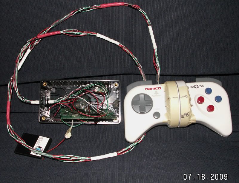
Just a little update of where I'm at with this thing..
Screwing up is one of the best learning tools, so long as the only thing you're not learning is how to screw up.
Re-mappable Wireless 360 Controller - The CGnome
Re-mappable Wireless 360 Controller - The CGnome
Re: PS3 Negcon Controller help pls
This one is about as done as it's gonna be for now. The buttons on the thing are Select, Home, L1/R1 and the Mode select for the Twist radius.

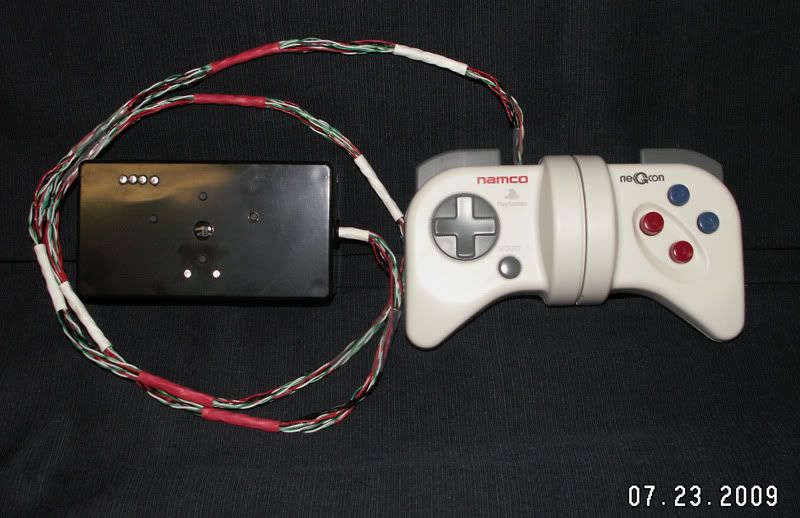
Video of the LEDs for the Twist Mode select changing when the button is pressed..

I would make up some vids of it in action, but holding that whole mess, trying to hit buttons and steering while looking at the camera to make sure the TV, neGcon and control box are all in screen and not have the CPU players mug me while I'm sitting there trying to get it all done just isn't gonna happen, I tried. The video of it working earlier is pretty much the same thing as now, just has 4 different max turn radius settings and is in a box instead of being a mess held together by the wiring.
Extra special thanks to Manta and DoJthis for all the work they did on the PIC/Math side of things, I just wave the soldering iron around.
If I ever mess with another one of these things I have a few more ideas to implement, with the main one being making the adapter so the neGcon isn't 'harmed' in any way and it can just be plugged up as-is (that's a HUGE undertaking there) customizable Twist settings and then BR+ (Barrel Rolls Plus) where ya only have to hit a direction once to do a BR, which is cheating in my book, like Rapid Fire, but figure it would be neat to try out since that type of adapter will have a lot more control over what's going on, but that's a whole other project to get into and has it's own set of challenges compared to this.
Video of the LEDs for the Twist Mode select changing when the button is pressed..
I would make up some vids of it in action, but holding that whole mess, trying to hit buttons and steering while looking at the camera to make sure the TV, neGcon and control box are all in screen and not have the CPU players mug me while I'm sitting there trying to get it all done just isn't gonna happen, I tried. The video of it working earlier is pretty much the same thing as now, just has 4 different max turn radius settings and is in a box instead of being a mess held together by the wiring.
Extra special thanks to Manta and DoJthis for all the work they did on the PIC/Math side of things, I just wave the soldering iron around.
If I ever mess with another one of these things I have a few more ideas to implement, with the main one being making the adapter so the neGcon isn't 'harmed' in any way and it can just be plugged up as-is (that's a HUGE undertaking there) customizable Twist settings and then BR+ (Barrel Rolls Plus) where ya only have to hit a direction once to do a BR, which is cheating in my book, like Rapid Fire, but figure it would be neat to try out since that type of adapter will have a lot more control over what's going on, but that's a whole other project to get into and has it's own set of challenges compared to this.
Screwing up is one of the best learning tools, so long as the only thing you're not learning is how to screw up.
Re-mappable Wireless 360 Controller - The CGnome
Re-mappable Wireless 360 Controller - The CGnome