Multiplayer?
SS
EDIT: Awesome pagebreak. Anyways, put up a pinout of the link port, when you figure it out, so I can add it to mine. :p
ss
*Gasp!* (see page 6 for LOB64 pinout!)
Moderator: Moderators
-
ShockSlayer
- Niblet 64
- Posts: 5059
- Joined: Thu Jun 29, 2006 12:47 pm
- Location: In my inbox.
Re: *Gasp!*
http://twitter.com/ShockSlayer" onclick="window.open(this.href);return false;
Re: *Gasp!*
Me too, please. 
If we all gather in the same place someday, I'm bringing GoldenEye and my N64p. ^_^
If you only need 6 of the wires, here's what you should do with the other two.

The transistors or whatever would be used for the auto-switching.
If we all gather in the same place someday, I'm bringing GoldenEye and my N64p. ^_^
If you only need 6 of the wires, here's what you should do with the other two.
The transistors or whatever would be used for the auto-switching.

Re: *Gasp!*
If I ever get around to building an N64 portable maybe I'll integrate this. I'm guessing you'll use RGB for the screen in your handheld and send composite over the line? Or composite for both?
We need a name for this standard. I'll field a few suggestions:
-Universal N64 Bus
-N64 Link Interface
-N64Wire
-LOB2009
-LOB64
-IEEE6400
We need a name for this standard. I'll field a few suggestions:
-Universal N64 Bus
-N64 Link Interface
-N64Wire
-LOB2009
-LOB64
-IEEE6400
-
Life of Brian
- Moderator
- Posts: 2867
- Joined: Wed Aug 03, 2005 5:55 pm
- Location: Oklahoma
- Contact:
Re: *Gasp!*
Personally I'm a fan of LOB64 but whatever we call it I think it's a great idea if we make a standard connector. I really don't think my portables will be done by MGC, but it would awesome to see the concept in action.
"What's that, you ask? It's just a LOB64 port, used to connect two N64 portables."
"What's that, you ask? It's just a LOB64 port, used to connect two N64 portables."
dragonhead wrote:sweet. ive spent a third of my life on benheck!


-
Life of Brian
- Moderator
- Posts: 2867
- Joined: Wed Aug 03, 2005 5:55 pm
- Location: Oklahoma
- Contact:
Re: *Gasp!*
Maybe I should post this in Technical Q&A, but this is a question about this specific portable and I'm making this my worklog so I'll post it here.
I successfully powered my N64 and screen off of a 7.4v battery on my first try. The PTH08000 worked exactly as promised, and I managed to get 3/4 of the way through some sweet StarFox action before I had to go do some errands. While playing, I noticed some annoying diagonal lines across the screen. They're not so bad as to be distracting, but I don't like them just the same. Does anyone know how to solve this problem? It was a freshly charged battery so it's not due to the battery running out of power.

Anybody know what level of StarFox that is?
Also, sidenote, I picked up a rapid Ni-Cd/Ni-MH battery charger from my local RadioShack on clearance for $6 (marked down from around $40). It charged my 3300mAh 7.4v Ni-MH battery so fast it was almost scary - about 5 minutes! I plan on using li-poly's for my N64 portables, but now that I have a super fast charger for my Ni-MH's I've just gotta use them for a portable. (Hey! I found a link on their website - it's marked at $5.97 there too! Get one!)
Aside from the joy I get out of playing StarFox, I also played it long enough to see how hot it could get. It did heat up quite a bit, but I think I can cut about 1/3 of the shielding off without a problem. I will have to think of where to place the batteries, however - I don't think I want to press some high capacity li-poly's right next to a hot metal plate and then cram it all together inside the case.
I successfully powered my N64 and screen off of a 7.4v battery on my first try. The PTH08000 worked exactly as promised, and I managed to get 3/4 of the way through some sweet StarFox action before I had to go do some errands. While playing, I noticed some annoying diagonal lines across the screen. They're not so bad as to be distracting, but I don't like them just the same. Does anyone know how to solve this problem? It was a freshly charged battery so it's not due to the battery running out of power.
Anybody know what level of StarFox that is?
Also, sidenote, I picked up a rapid Ni-Cd/Ni-MH battery charger from my local RadioShack on clearance for $6 (marked down from around $40). It charged my 3300mAh 7.4v Ni-MH battery so fast it was almost scary - about 5 minutes! I plan on using li-poly's for my N64 portables, but now that I have a super fast charger for my Ni-MH's I've just gotta use them for a portable. (Hey! I found a link on their website - it's marked at $5.97 there too! Get one!)
Aside from the joy I get out of playing StarFox, I also played it long enough to see how hot it could get. It did heat up quite a bit, but I think I can cut about 1/3 of the shielding off without a problem. I will have to think of where to place the batteries, however - I don't think I want to press some high capacity li-poly's right next to a hot metal plate and then cram it all together inside the case.
dragonhead wrote:sweet. ive spent a third of my life on benheck!
-
marshallh
- Moderator
- Posts: 2987
- Joined: Sat Sep 10, 2005 2:17 pm
- 360 GamerTag: marshallh
- Location: here and there
- Contact:
Re: *Gasp!*
Had the same problem myself. You need to put a coil/choke on the power wire going to the LCD. You do this by wiring a diode and a coil in in parallel, and attach the mess in series sometime before that 7.5v line goes to the LCD power. Make sure your diode is facing the right way

-
eagle5953
- Moderator
- Posts: 1892
- Joined: Mon Jul 07, 2008 5:06 pm
- 360 GamerTag: eagle5953
- Steam ID: eagle5953
- Contact:
Re: *Gasp!*
Fantastic concepts and application! I'm really looking forward to seeing this completed.
The idea of multiplayer over Cat-5 is mind-boggling. That could be implemented even in non-portables.
The idea of multiplayer over Cat-5 is mind-boggling. That could be implemented even in non-portables.
-
ShockSlayer
- Niblet 64
- Posts: 5059
- Joined: Thu Jun 29, 2006 12:47 pm
- Location: In my inbox.
Re: *Gasp!*
That's not how I fixed it. You can do multiple things. I would check your Composite wire(if thats what you're using) I switched out mine with the original video wire(with the ground sheilding inside), and actually connected ground to ground. Worked great. If all else failed, try folding some aluminum foil into 4 layers worth of...foil, and then connect it to ground, and then press it up to the back of your screen. After wrapping it in electrical tape.
Simply saying, my guess it that it's interference. I don't know what the marshallh guy is talking about with a coil and A diode and whatnot, I doubt its your 7.2v line.
Someone correct me if I'm being stupid, I'm kinda tired
SS
Simply saying, my guess it that it's interference. I don't know what the marshallh guy is talking about with a coil and A diode and whatnot, I doubt its your 7.2v line.
Someone correct me if I'm being stupid, I'm kinda tired
SS
http://twitter.com/ShockSlayer" onclick="window.open(this.href);return false;
-
Life of Brian
- Moderator
- Posts: 2867
- Joined: Wed Aug 03, 2005 5:55 pm
- Location: Oklahoma
- Contact:
Re: *Gasp!*
SS, you're proposing pretty much the same thing marshallh is - cutting down on interference, whether it's on the power line or the video line.
Any chance I can be lazy and use a snap on choke like this? If not, does anyone know if this little guy would be sufficient?
Another quick question - if I included a diode bridge (a.k.a. bridge rectifier) in my portable between the power jack and my system, does that mean I could use any wall wart (with proper voltage and current) without worrying about the polarity being correct? It looks like it would be pretty easy to include, and if I ever developed portablizing into a business I would probably want to include that.
Any chance I can be lazy and use a snap on choke like this? If not, does anyone know if this little guy would be sufficient?
Another quick question - if I included a diode bridge (a.k.a. bridge rectifier) in my portable between the power jack and my system, does that mean I could use any wall wart (with proper voltage and current) without worrying about the polarity being correct? It looks like it would be pretty easy to include, and if I ever developed portablizing into a business I would probably want to include that.
dragonhead wrote:sweet. ive spent a third of my life on benheck!
Re: *Gasp!*
First question- you want to install some filtering caps on the power lines as close to the devices as possible.
Second question- I think a bridge rectifier will work. An added bonus is that you can use an AC supply (but beware of the voltage increase).
Can you buy me one of those chargers? There's no radioshack in Canada.
EDIT: Where's the LOB64 pinout?!
Second question- I think a bridge rectifier will work. An added bonus is that you can use an AC supply (but beware of the voltage increase).
Can you buy me one of those chargers? There's no radioshack in Canada.
EDIT: Where's the LOB64 pinout?!
-
Life of Brian
- Moderator
- Posts: 2867
- Joined: Wed Aug 03, 2005 5:55 pm
- Location: Oklahoma
- Contact:
Re: *Gasp!*
XCVG - do you have any more specific information than "filtering caps"? If not I'll try the RF shielding approach first. As for a pinout of the LOB64 interface, Mario and I have been kicking around some ideas through PM's. I'll post more info about it soon.
dragonhead wrote:sweet. ive spent a third of my life on benheck!
Re: *Gasp!*
Just solder some little ceramic caps across the power terminals. You could try putting them between video and ground but I have NO idea what effect that would have. You could try some big electrolytics too.
-
Life of Brian
- Moderator
- Posts: 2867
- Joined: Wed Aug 03, 2005 5:55 pm
- Location: Oklahoma
- Contact:
Re: *Gasp!*
There is probably not too much risk, but I would really appreciate it if anyone could give me some actual values or a range to work within about the suggested filtering ideas.
Okay - before going to sleep last night and after discussing some ideas with Mario through a few PM's, I quickly drew up an initial schematic for the LOB64 interface. I woke up this morning and MS Paint'ed it.

Corresponding RJ45 pinout:
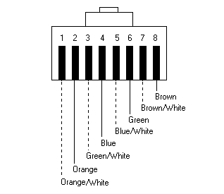
^image borrowed from: http://www.simulationexams.com/tutorial ... ectors.htm
After trying to come up with some clever use of relays or transistors to get some sort of automatic sensing of whether the portable was in Master mode or Slave and turn off the N64 while keeping the screen on, I realized I could just as easily add a lever switch in the cartridge slot to get the same effect.
Since I have the TI regulator in before the lever switch but after the main power switch, the onboard controller can still be powered by the portable's own battery along with the screen when in Slave mode. In order to choose which portable is player one or player two (or three or four), a DIP switch or rotary switch (or a rotary DIP switch - imagine that) is needed between the onboard controller and the LOB64 port.
I didn't draw the connections to ground for the controller or the regulator, but they connect to ground like always.
It's about as elegant a setup as I am able to create at my skill level. If any of you with some actual EE training can think of a simpler/cooler circuit then I'm all ears
Edit: It seems that a double post lever switch is kind of rare - I can't find any cheap ones online. Either I could just include two single post lever switches, or some other setup is needed. Regardless of how it's done, the main point is that the presence of a cartridge in the system determines whether the portable is in Master or Slave mode.
Okay - before going to sleep last night and after discussing some ideas with Mario through a few PM's, I quickly drew up an initial schematic for the LOB64 interface. I woke up this morning and MS Paint'ed it.
Corresponding RJ45 pinout:
^image borrowed from: http://www.simulationexams.com/tutorial ... ectors.htm
After trying to come up with some clever use of relays or transistors to get some sort of automatic sensing of whether the portable was in Master mode or Slave and turn off the N64 while keeping the screen on, I realized I could just as easily add a lever switch in the cartridge slot to get the same effect.
Since I have the TI regulator in before the lever switch but after the main power switch, the onboard controller can still be powered by the portable's own battery along with the screen when in Slave mode. In order to choose which portable is player one or player two (or three or four), a DIP switch or rotary switch (or a rotary DIP switch - imagine that) is needed between the onboard controller and the LOB64 port.
I didn't draw the connections to ground for the controller or the regulator, but they connect to ground like always.
It's about as elegant a setup as I am able to create at my skill level. If any of you with some actual EE training can think of a simpler/cooler circuit then I'm all ears
Edit: It seems that a double post lever switch is kind of rare - I can't find any cheap ones online. Either I could just include two single post lever switches, or some other setup is needed. Regardless of how it's done, the main point is that the presence of a cartridge in the system determines whether the portable is in Master or Slave mode.
Last edited by Life of Brian on Wed Feb 18, 2009 11:15 am, edited 3 times in total.
dragonhead wrote:sweet. ive spent a third of my life on benheck!
-
eagle5953
- Moderator
- Posts: 1892
- Joined: Mon Jul 07, 2008 5:06 pm
- 360 GamerTag: eagle5953
- Steam ID: eagle5953
- Contact:
Re: *Gasp!* (see page 2 for LOB64 pinout!)
If I'm ever skilled enough to do an N64p, I'm going to need to do this. Amazing.
Last edited by eagle5953 on Wed Feb 18, 2009 1:08 pm, edited 1 time in total.