SS's WIP GCP!

Includes PS2, Xbox 1, GameCube (but not the Phantom Game Console)

Moderator: Moderators

Post Reply
ShockSlayer
Niblet 64
Posts: 5059
Joined: Thu Jun 29, 2006 12:47 pm
Location: In my inbox.

Post by ShockSlayer »

Ah, I see! :D

SS
http://twitter.com/ShockSlayer" onclick="window.open(this.href);return false;
Mario
Posts: 1383
Joined: Mon Mar 05, 2007 7:20 pm
Location: Sunny California

Post by Mario »

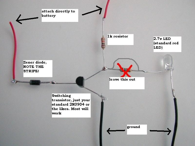
Okay ppl, here you go. Note that this is different than the schematic I posted - I found there was a couple errors with it. Here is how you should build this:
EDIT: Look a little further down the page for another correction.
Image

Note how the diode is facing. The stripe MUST be facing toward the battery or it will not work. Also, the LED resistor must be changed, since there is already a 10k resistor before it, but who knows, it might work. I need someone to test this for me! The red wires go to the + terminal of the battery, the black ones go to ground.
Last edited by Mario on Fri Jan 09, 2009 7:39 pm, edited 1 time in total.
Image
ShockSlayer
Niblet 64
Posts: 5059
Joined: Thu Jun 29, 2006 12:47 pm
Location: In my inbox.

Post by ShockSlayer »

Do I need to use the external 5v for the led if it can be powered from the source, since this is a 12v led?
http://twitter.com/ShockSlayer" onclick="window.open(this.href);return false;
Mario
Posts: 1383
Joined: Mon Mar 05, 2007 7:20 pm
Location: Sunny California

Post by Mario »

You connect both red wires straight to the battery. The problem with this design is, the 10k resistor is before the LED, so it acts a a current limiting resistor. You'd better use like a 3v LED.
Image
ShockSlayer
Niblet 64
Posts: 5059
Joined: Thu Jun 29, 2006 12:47 pm
Location: In my inbox.

Post by ShockSlayer »

Mario wrote:You connect both red wires straight to the battery. The problem with this design is, the 10k resistor is before the LED, so it acts a a current limiting resistor. You'd better use like a 3v LED.
Okay, I'll try that. It looks like you used different resistors, I caught the 1k ohm one, what about the other? is that 5.6k?
Last edited by ShockSlayer on Fri Jan 09, 2009 6:51 pm, edited 1 time in total.
http://twitter.com/ShockSlayer" onclick="window.open(this.href);return false;
Mario
Posts: 1383
Joined: Mon Mar 05, 2007 7:20 pm
Location: Sunny California

Post by Mario »

Well, I really don't know how much of a load the battery needs, but I know you need a resistor otherwise the battery is just going to be shorted all the time. (When the LED is off) The other one I think it should be 10k, but I'm not sure...

EDIT: Hold on a sec, I'm going to go test how low resistance you can go before it really is shorting the battery.
Image
ShockSlayer
Niblet 64
Posts: 5059
Joined: Thu Jun 29, 2006 12:47 pm
Location: In my inbox.

Post by ShockSlayer »

Okay. I'll be right back, going to go rewire mine. I found a random transistor...

The way I am testing this, is, I have it connected to a plug, which can connect to a fully charged 11.1v battery, and that should have no led on. And then with the same plug connecting it to a 7.4v battery, and the led should be on.

SS
http://twitter.com/ShockSlayer" onclick="window.open(this.href);return false;
Mario
Posts: 1383
Joined: Mon Mar 05, 2007 7:20 pm
Location: Sunny California

Post by Mario »

Right, but make sure you have a switching transistor - either 2N3904, 2N2222, or 2N4401.
Image
ShockSlayer
Niblet 64
Posts: 5059
Joined: Thu Jun 29, 2006 12:47 pm
Location: In my inbox.

Post by ShockSlayer »

Mario wrote:Right, but make sure you have a switching transistor - either 2N3904, 2N2222, or 2N4401.
Well, I don't know. I guess I got lucky, because: I finished my circuit(exact same as yours, except with a 10k Resistor, and hooked it up to my 11.1v, I got nuthin, and then my 7.4v, and the LED came on! YAYZ!

Thoughts?

SS

EDIT: the transistor says:

NEC
C1093
A829D

Not sure if that last digit is a d or an o

SS
http://twitter.com/ShockSlayer" onclick="window.open(this.href);return false;
Mario
Posts: 1383
Joined: Mon Mar 05, 2007 7:20 pm
Location: Sunny California

Post by Mario »

Guess it must be a switching transistor, then. You used a 10k for the current limiter? And your LED was a full brightness? I found that you should use a 1W 1k resistor for the current resistor and omit the LED resistor. So like this:
Image

I was testing different resistor values and I tried a 33ohm one. I hooked it up to my 12v 2A power source and after a second decided it a good idea to grab it to feel if it was hot at all. Here's a tip: Don't, unless you enjoy 2nd degree burns. :( :lol:
Image
ShockSlayer
Niblet 64
Posts: 5059
Joined: Thu Jun 29, 2006 12:47 pm
Location: In my inbox.

Post by ShockSlayer »

Ouch. :?

Yeah, it was a blue LED. Nice and bright. Lights up for a half second everytime I turn it on or off. Which rocks. :P

I can't wait till my battery is about to die! :lol:

SS

EDIT: I'm going to throw that picture into the sticky. Might be useful for others, who need status indicators.
http://twitter.com/ShockSlayer" onclick="window.open(this.href);return false;
Mario
Posts: 1383
Joined: Mon Mar 05, 2007 7:20 pm
Location: Sunny California

Post by Mario »

A huh huh huh! :)

Make sure you're monitoring that battery voltage with your multimeter when it gets low so you know at what battery voltage the LED lights up and how much longer you have after that. You could videotape it if you get tired of waiting. :wink:

In a perfect world, the LED should light up at 10.2 v, because you got two 5.1v diodes, however, they are made with slight tolerances, so the LED might actually go on at 10v or 9.9v, in which case you would add a small resistor (maybe 2.2k) before the diodes.
Image
ShockSlayer
Niblet 64
Posts: 5059
Joined: Thu Jun 29, 2006 12:47 pm
Location: In my inbox.

Post by ShockSlayer »

Or, I could run my portable until it dies, and time how long it takes to die after the led comes on! :P (which is what I'm doing right now) If it dies before LED turns on, then I need to add a resistor.

:wink:

SS
http://twitter.com/ShockSlayer" onclick="window.open(this.href);return false;
Mario
Posts: 1383
Joined: Mon Mar 05, 2007 7:20 pm
Location: Sunny California

Post by Mario »

You've got it. :) You may get bored of waiting, though, so that's why I said you should videotape it. :P

EDIT: Just saw your edit:
"EDIT: I'm going to throw that picture into the sticky. Might be useful for others, who need status indicators."

I'm also going to write a guide for that, so be looking for it.
Image
ShockSlayer
Niblet 64
Posts: 5059
Joined: Thu Jun 29, 2006 12:47 pm
Location: In my inbox.

Post by ShockSlayer »

Mario wrote:You've got it. :) You may get bored of waiting, though, so that's why I said you should videotape it. :P

EDIT: Just saw your edit:
"EDIT: I'm going to throw that picture into the sticky. Might be useful for others, who need status indicators."

I'm also going to write a guide for that, so be looking for it.
Great!

I wont be bored if I'm actually USING the portable! :lol:

SS
http://twitter.com/ShockSlayer" onclick="window.open(this.href);return false;
Post Reply