You have to send in a HOW-TO also... This could be revolutionary to the entire being of portables...
either that or I think its cool.
Guess what this is...
Moderator: Moderators
-
SpongeBuell
- Senior Member
- Posts: 5190
- Joined: Wed Apr 07, 2004 10:52 am
- Location: Colorado
- Contact:
I'd say this is the best thing since Ben discovered the NOAC in the Super Joys, and that's pretty good.Geebs61 wrote:You have to send in a HOW-TO also... This could be revolutionary to the entire being of portables...
either that or I think its cool.
Life of Brian wrote:I'll be honest with you - I would have never guessed that.RYW wrote:RYW:
Rare
Yellow
Weasel
-
wasted_druid
- Posts: 41
- Joined: Wed Apr 07, 2004 2:18 pm
Nah, I though infared would be really stupid. Cheaper, but stupid. It's RF. Luckily I didn't have to do any of the hard rf circuitry. I found an inexpensive transmitter module that's smaller than a postage stamp. The reciever is a touch bigger (narrower than a postage stamp in one axis, but wider in the other). The biggest things are actually the 8 bit encoder/decoder ICs. It would work for the atari joystic as well, but I don't really know how the paddle works, so I don't know if I could get that to work. And like I said, I don't know what the response time on the buttons is. I'm going to try to rig up a makeshift controller tonight (I don't have any switches, so this could be tricky, although I have a couple ideas) and see if it's playable. Hopefully my half portabalized/abandoned NES is still functional. I was going to get myself a NOAC, but my job just ran dry and I'm out of money.Hmmm... I hope I can find another 7805 lying around somewhere... and I haven't found any 16 bit encoder/decoders yet, so I don't know how to do an snes, and anything that has analog joysticks, is getting far beyond my desire to design. Probably cheaper just to buy a commercial one.
Enough rambling.
Enough rambling.
-
wasted_druid
- Posts: 41
- Joined: Wed Apr 07, 2004 2:18 pm
For the NES I really only need communication to go 1 way...
In an NES controller, the 8 switches connect to a bit shift register (or something like that bear with me) when the NES sends a certain signal to the chip, it freezes it's inputs, then feeds them out to the NES one at a time, with each pulse of the clock. Then it resets and waits for the next freeze signal from the NES. At first I thought I would have to find a way to transmit the freeze signal, and the clock, but then I found a more elegant solution. There were readymade chips for encoding/decoding 8 parallel bits. I took the bit shift register out of the controller half of things, so all the controller does is send 8 bits... on off on on off etc... The reciver circuit picks that up, then the decoder chip gives me the same out the 8 parallel bits (the ones that I sent). So I feed those 8 bits into the bit shift register as if it were just the input from the switches. It can't tell the difference, and since the bit shift register is the only thing that needs info from the NES and it's on the reciever side of things, I don't need to broadcast any info from the NES. One-way communication is what makes my design easy and feasible.
(Another note: instead of using pull up resistors to invert the logic from my switches, I'm going to use a couple of hex inverters. I can either put them in the controller between the switches and the encoder or on the reciever between the decoder and the bit shift register. I'm thinking controller, since I've got more room there, since the circuit is really small on that side of things.)
In an NES controller, the 8 switches connect to a bit shift register (or something like that bear with me) when the NES sends a certain signal to the chip, it freezes it's inputs, then feeds them out to the NES one at a time, with each pulse of the clock. Then it resets and waits for the next freeze signal from the NES. At first I thought I would have to find a way to transmit the freeze signal, and the clock, but then I found a more elegant solution. There were readymade chips for encoding/decoding 8 parallel bits. I took the bit shift register out of the controller half of things, so all the controller does is send 8 bits... on off on on off etc... The reciver circuit picks that up, then the decoder chip gives me the same out the 8 parallel bits (the ones that I sent). So I feed those 8 bits into the bit shift register as if it were just the input from the switches. It can't tell the difference, and since the bit shift register is the only thing that needs info from the NES and it's on the reciever side of things, I don't need to broadcast any info from the NES. One-way communication is what makes my design easy and feasible.
(Another note: instead of using pull up resistors to invert the logic from my switches, I'm going to use a couple of hex inverters. I can either put them in the controller between the switches and the encoder or on the reciever between the decoder and the bit shift register. I'm thinking controller, since I've got more room there, since the circuit is really small on that side of things.)
-
wasted_druid
- Posts: 41
- Joined: Wed Apr 07, 2004 2:18 pm
You can get small DC-DC converters that will let you use 1 AAA. Fixup uses one in the headphone amps he sells. Some pictures in this thread.
Or, depending on the current draw, you can use supercapacitors. You'll still need a DC-DC converter to keep a steady voltage, but you can make them tiny. They won't last hours on end, but you can recharge them in seconds.
You could also strap a cell phone battery to the back, if you can find a battery and charger cheap.
Or, depending on the current draw, you can use supercapacitors. You'll still need a DC-DC converter to keep a steady voltage, but you can make them tiny. They won't last hours on end, but you can recharge them in seconds.
You could also strap a cell phone battery to the back, if you can find a battery and charger cheap.

-
···Agent EQzE···
- Posts: 29
- Joined: Sun May 02, 2004 7:08 am
- Contact:
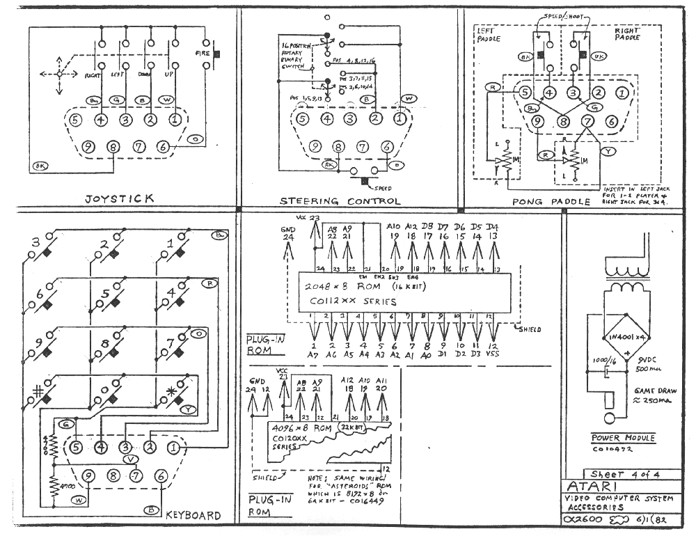
This would be worth looking at: http://users.erols.com/tiltonj/games/te ... tml#paddlewasted_druid wrote:It would work for the atari joystic as well, but I don't really know how the paddle works, so I don't know if I could get that to work.
-
wasted_druid
- Posts: 41
- Joined: Wed Apr 07, 2004 2:18 pm
Just as I thought. The paddles are complicated... I'd need an A/D converter and a D/A converter. I'd only do one paddle, not two, So, I'd need 1 bit for the button, then 7 bits left over for the potentiometer. That's (looks at his fingers to be sure) 128 possible positions... I don't know, think that'd be enough resolution for the paddle?