Metal Slug R0X!!!
have you played 2020 Super Baseball? It's pretty good, very fast paced. They have it at a gamestore for $20. This is a Neo Geo game, so I'm not surprised
I'm thinking about making Atari 2600 PCB's
Moderator: Moderators
-
SpongeBuell
- Senior Member
- Posts: 5190
- Joined: Wed Apr 07, 2004 10:52 am
- Location: Colorado
- Contact:
-
A.J. Franzman
- Posts: 216
- Joined: Mon Jan 17, 2005 11:38 pm
- Location: La-La Land
- Contact:
I use a different method, a lot less toasty and stinky (and less likely to get lead all over the place): 100/150 watt soldering gun. Take some bare 12 gauge solid electrical wire, and use pliers to make a rectangular loop the right width to touch the pins on the sides of the IC and a bit longer than the IC you want to remove, and screw that into the gun in place of the regular soldering tip. You will also need some liquid or paste flux, fine rosin-core solder wire, an IC extractor, small blade screwdriver and/or similar soldering helper tool.JackFrost22 wrote:I dont like killing things and its hard to desolder stuff without burning it out. Oh and heres something I found out frim an electronics guru. To remove a chip that will get fried if you desolder it. Take a blowtorch put it on one side of the board anmd pry with a screwdiver the chip off
You will probably want to experiment with the loop shape so it plugs in the gun and is convenient to hold against the chip pins (from either the top or bottom of the board). Once you have the shape right, switch on at high heat and "tin" it with solder on the sides that will touch the chip pins. Remove any other components near the IC that get in the way as necessary (using your regular pencil-type soldering iron).
Be sure the IC pins are not bent on the bottom of the board. You can straighten them one at a time with the screwdriver or soldering tool and your pencil iron if necessary. Apply flux along the 2 rows of pins on the side you want to apply the iron. Clip the IC extractor to the chip. Heat the loop up on high for 30 seconds or so before placing it across the IC, then use the fine solder to fill any gaps where your custom chip remover iron doesn't quite touch the pins and flow the solder. A bit of jiggling and/or sliding the loop back and forth may help here (that's why I had you make the loop longer than the IC). In 20 seconds or so the solder on all the pins should flow and allow you to neatly pull out the IC. Sometimes the pins on one side or corner won't let go - in this case, re-position the hot loop so it only touches the side still stuck to the board, and check to see if you need to apply a bit more solder. You can also try heating from the other side of the board.
If you're worried about cooking your IC this way, forget it! I've pulled hundreds this way and haven't cooked any yet, even some that took over a minute to get loose. Don't worry about the power in the iron zapping the IC either - the part that heats up only gets to about 2 1/2 volts on the high power setting; it's a lot of CURRENT that heats the wire, not volts!
If you're pulling a bunch of chips and start to notice you're having trouble getting the solder to melt, loosen and retighten the screws holding your custom tip a few times - they need to make firm contact to shiny metal, otherwise you just heat up the screws instead of the wire loop.
Last edited by A.J. Franzman on Wed Jan 19, 2005 11:30 pm, edited 1 time in total.
Mum! Dad! Don't touch it! It's EEE-VIL!
WTD: Donated dead Atari 2600 consoles, mobos, or their ICs.
2600 NTSC cartridges and manuals.
Click for TRADE/SELL and WANTED lists.
WTD: Donated dead Atari 2600 consoles, mobos, or their ICs.
2600 NTSC cartridges and manuals.
Click for TRADE/SELL and WANTED lists.
-
A.J. Franzman
- Posts: 216
- Joined: Mon Jan 17, 2005 11:38 pm
- Location: La-La Land
- Contact:
Well, are you trying to make a "proper" composite converter like Kevin Horton did, or just adapt the "2 pots and a resistor" method to the board? I read somewhere that you shouldn't need to use pots - the resistor values are supposed to exactly double (22, 44, and 88 ohms? but in what order I don't remember).benheckc wrote:I'm wondering, what does the video circuit require since it's going to be composite? Anyone?
You could confirm this by carefully disconnecting them from a few properly adjusted units and measuring. Replacing pots with fixed resistors will probably require use of precision 1% resistors to get the right values, but the nice thing about them is you can order almost any value you like with 3 decimals of precision. Also, if you find the values are fairly consistent but you don't want to use fixed resistors, 1k ohm pots are too big - adjusment would be much easier with smaller pots like 120, 150, 220, or even 500 ohms - whatever's available and cheap.
Mum! Dad! Don't touch it! It's EEE-VIL!
WTD: Donated dead Atari 2600 consoles, mobos, or their ICs.
2600 NTSC cartridges and manuals.
Click for TRADE/SELL and WANTED lists.
WTD: Donated dead Atari 2600 consoles, mobos, or their ICs.
2600 NTSC cartridges and manuals.
Click for TRADE/SELL and WANTED lists.
-
SgtBowhack
- Posts: 831
- Joined: Wed Dec 08, 2004 5:16 am
- Location: Chicago, USA
As far as desoldering components goes, if you put it in your wave soldering toaster oven, you can put it in there for a minute or so and then just pull the components off. They should come off pretty clean. The trick is getting your hand into the oven in the right spot to pull whatever you want off (which may mean you'll need to be smart in placing it into the toaster in the first place). I plan on trying this when I replace some capacitors on an old motherboard.

-
A.J. Franzman
- Posts: 216
- Joined: Mon Jan 17, 2005 11:38 pm
- Location: La-La Land
- Contact:
I've heard of *reflow* soldering in a toaster oven, but not wave soldering...

Mum! Dad! Don't touch it! It's EEE-VIL!
WTD: Donated dead Atari 2600 consoles, mobos, or their ICs.
2600 NTSC cartridges and manuals.
Click for TRADE/SELL and WANTED lists.
WTD: Donated dead Atari 2600 consoles, mobos, or their ICs.
2600 NTSC cartridges and manuals.
Click for TRADE/SELL and WANTED lists.
-
SgtBowhack
- Posts: 831
- Joined: Wed Dec 08, 2004 5:16 am
- Location: Chicago, USA

-
Guest
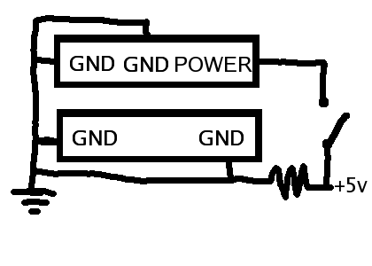
http://www.seattlerobotics.org/encoder/ ... asics.htmlHK-47 wrote:Can we see this circut?Also you will need to add the small circut for the pull-down resistor to detect a normal cart being inserted and short the 5v going to the multi cart.
this page will show you how a pull down resistor works.
use it to send +5v or GND to the onboard game or games.
You can use a switch to turn them on or off or use the cart port.
The cart port has 2 gnd lines going to it from the mother board. Cut one and conect to +5v with the pulldown resistor.
So when there is no cart the +5v goes to the onboard game or games.
When a cart is put in the cart port GND will get conected to the +5v mod that you did and short across the pulldown resistor.
That will change the +5v going to the onboard games to GND.
-
JackFrost22
- Sir Posts-alot
- Posts: 4186
- Joined: Fri Jun 04, 2004 4:10 pm
Also the last post was mine
They were quick and good quality.
But here is an idea.
Instead of spending money having someone make them for you.
You might just be able to use the laser etcher that you have.
I don't know what type it is but my friend uses the one at his work to etch boards with.
The software that you have should scribe as well as cut.
I know that some software will cut on a line and scribe on a fill in the CAD drawing.
Just a thought.
I could also try a test board for you.
I use the same software and have used their quick small board service.benheckc wrote:I'm using the ExpressPCB software, haven't tried their service yet. For prototyping the price seems OK, but what about larger runs?
They were quick and good quality.
But here is an idea.
Instead of spending money having someone make them for you.
You might just be able to use the laser etcher that you have.
I don't know what type it is but my friend uses the one at his work to etch boards with.
The software that you have should scribe as well as cut.
I know that some software will cut on a line and scribe on a fill in the CAD drawing.
Just a thought.
I could also try a test board for you.
Thanks dude!Anonymous wrote:http://www.seattlerobotics.org/encoder/ ... asics.htmlHK-47 wrote:Can we see this circut?Also you will need to add the small circut for the pull-down resistor to detect a normal cart being inserted and short the 5v going to the multi cart.
this page will show you how a pull down resistor works.
use it to send +5v or GND to the onboard game or games.
You can use a switch to turn them on or off or use the cart port.
The cart port has 2 gnd lines going to it from the mother board. Cut one and conect to +5v with the pulldown resistor.
So when there is no cart the +5v goes to the onboard game or games.
When a cart is put in the cart port GND will get conected to the +5v mod that you did and short across the pulldown resistor.
That will change the +5v going to the onboard games to GND.

-
JackFrost22
- Sir Posts-alot
- Posts: 4186
- Joined: Fri Jun 04, 2004 4:10 pm