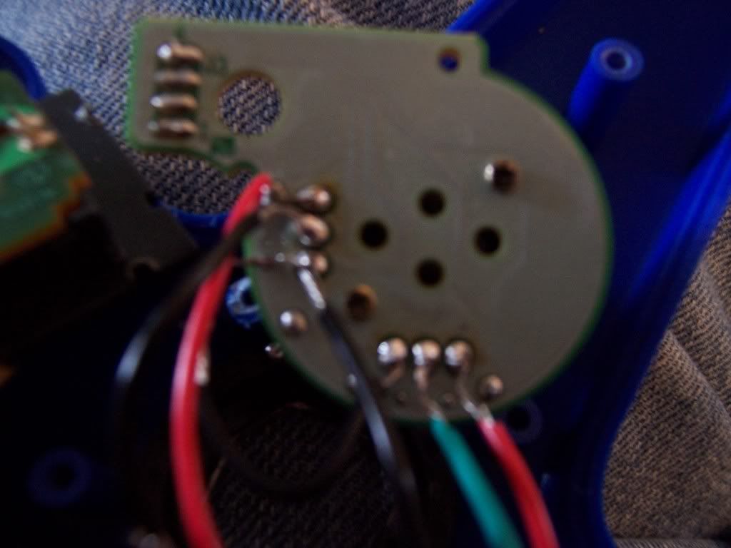
This is viewing it upside down - looking at it normally, the X axis is on top, and the Y axis is on the right. Is this how it should be set up? (on the original GC c stick, the y is on left, and x on bottom)
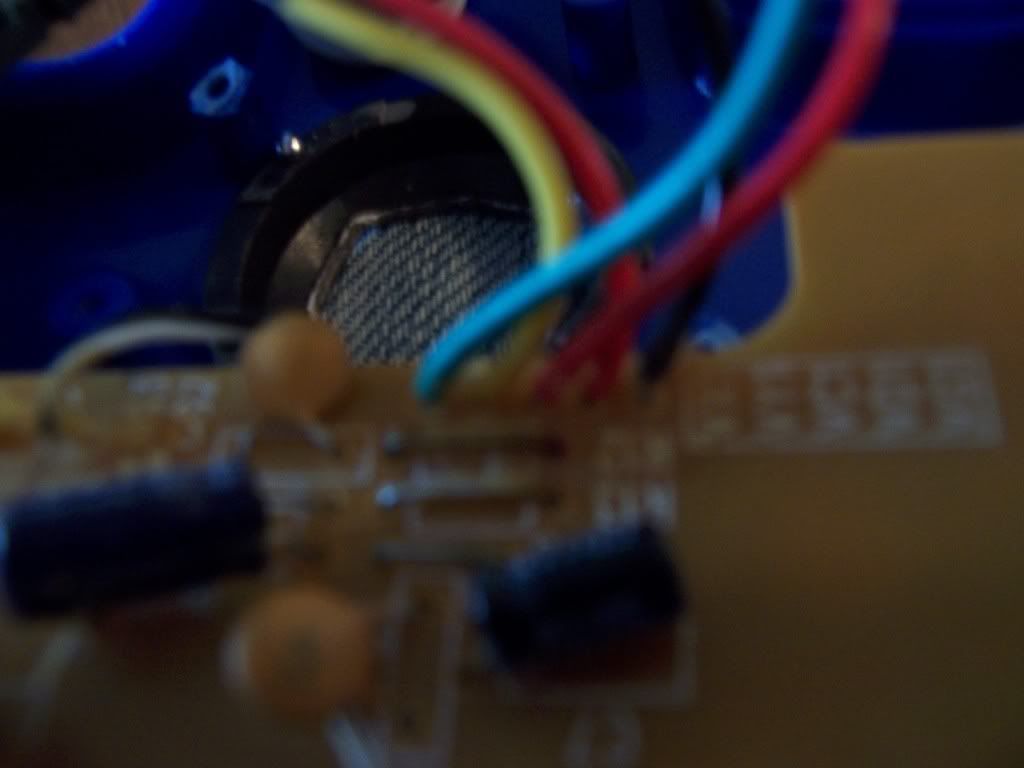
This is a close up of the 5 wires coming out of the controller (also upside down view). Sorry it's kinda dark.
Looking at it normally, from the left, the wires are in this order:
VG1 (black), VD1 (red), VC1 (red), VY1 (yellow/black), VX1 (green)
I soldered it like shown in the picture (x on top, y on right), and the connections all looked pretty good. If you can't see in the picture, I have 2 connections on the corner of the Y axis closest to X for the initial ground connection, and a separate wire from there as well leading to the X corner. The VX1 green is in the middle X, and the VY1 yellow/black is in the middle Y. The VD1 red wire is connected to the last Y slot, and the VC1 orther red wire is in the other X slot.
Plugged it into my N64 and it shut off right away again and went back into its sleep/scared of foreign devices mode.
Again, this is the SuperPad64 by Performance (blue).
Any suggestions?
