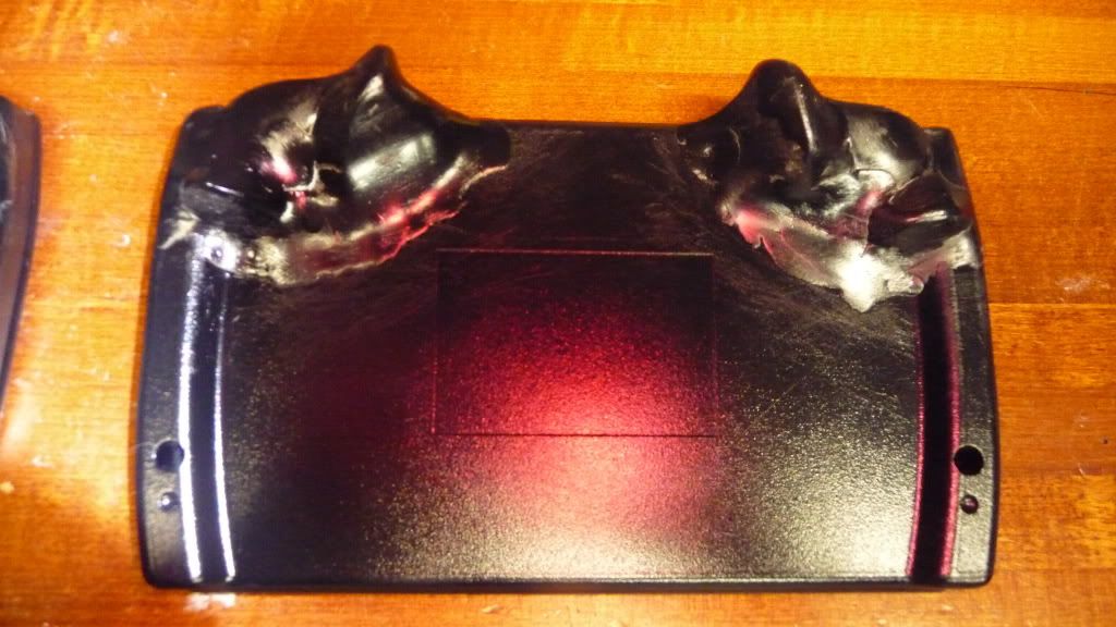
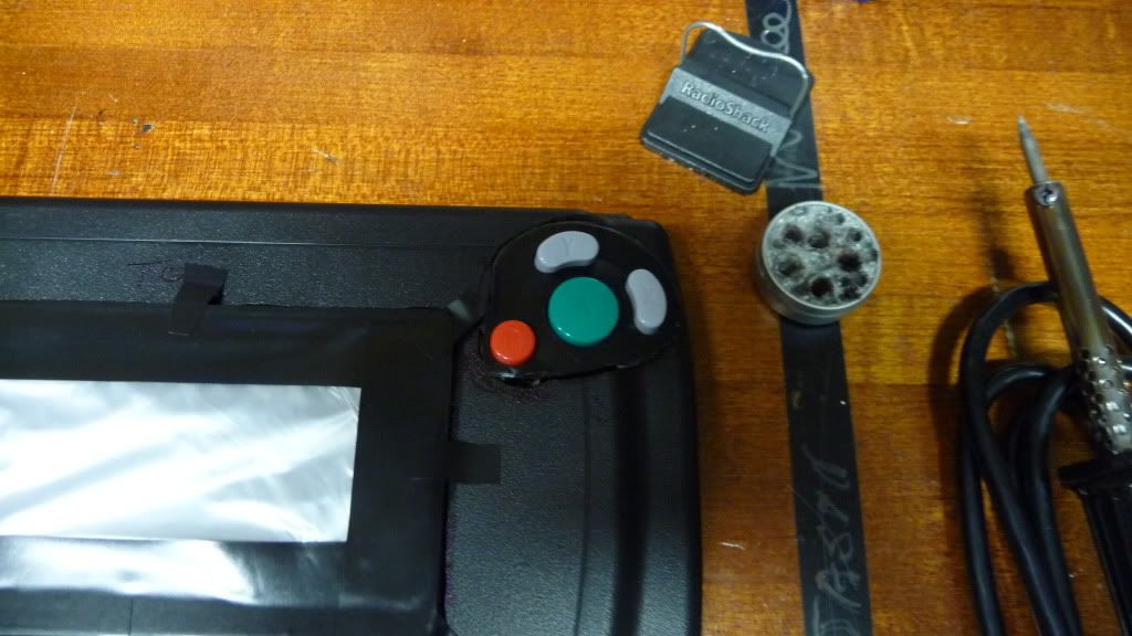
I haven't decided on a name yet, although I'm probably going to paint it black.
Specs
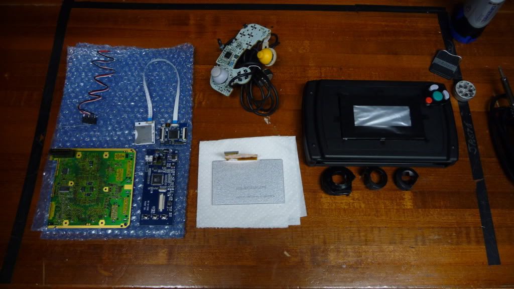
-4.3" ebay screen
-WiiKey Fusion
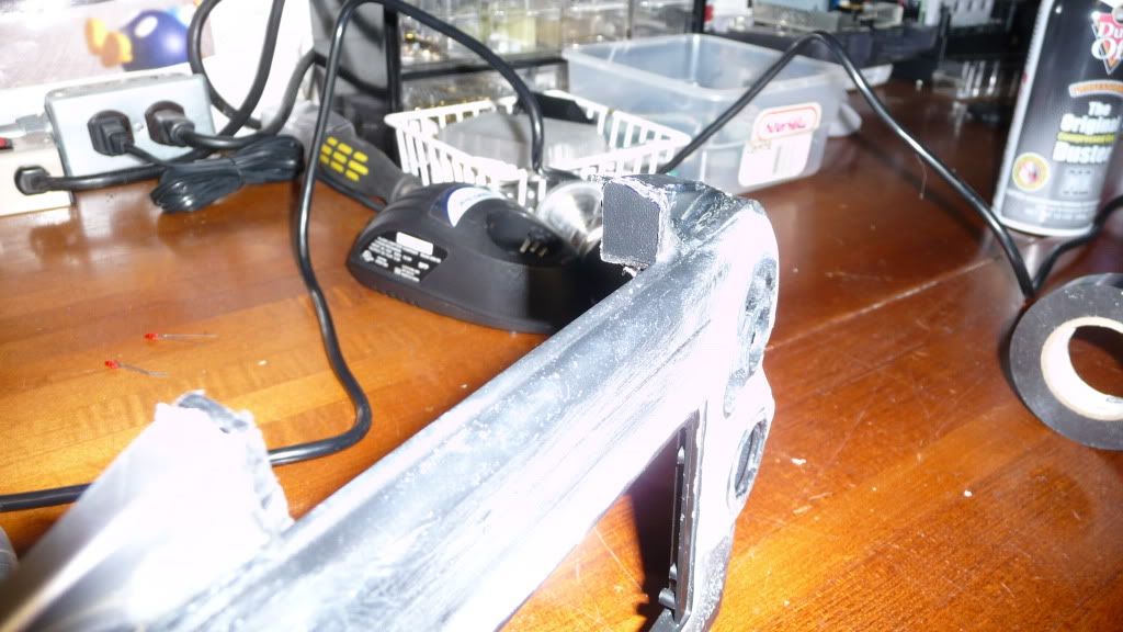
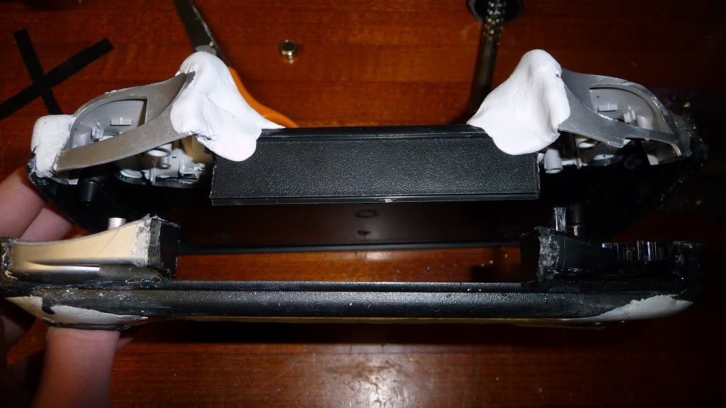
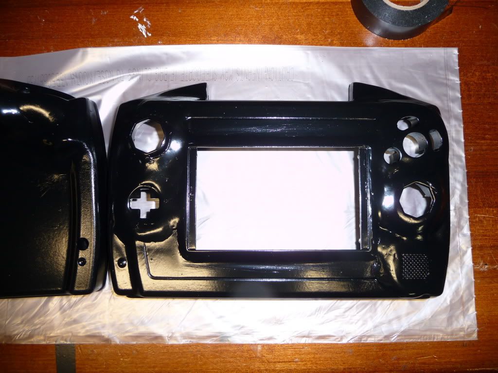
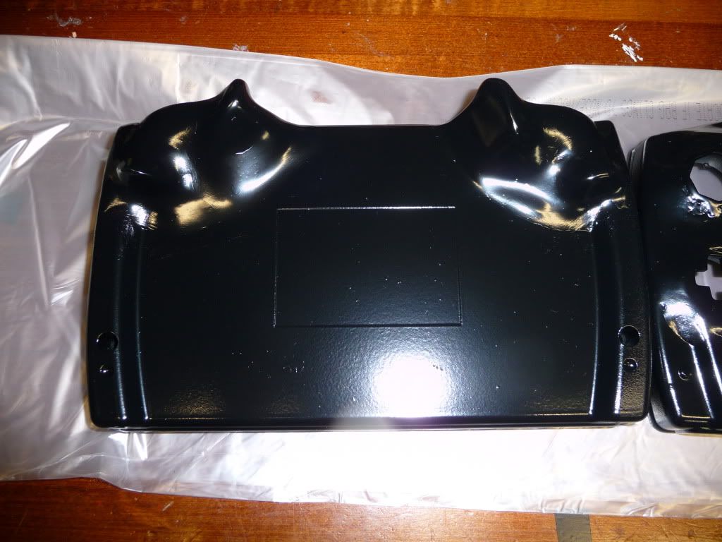
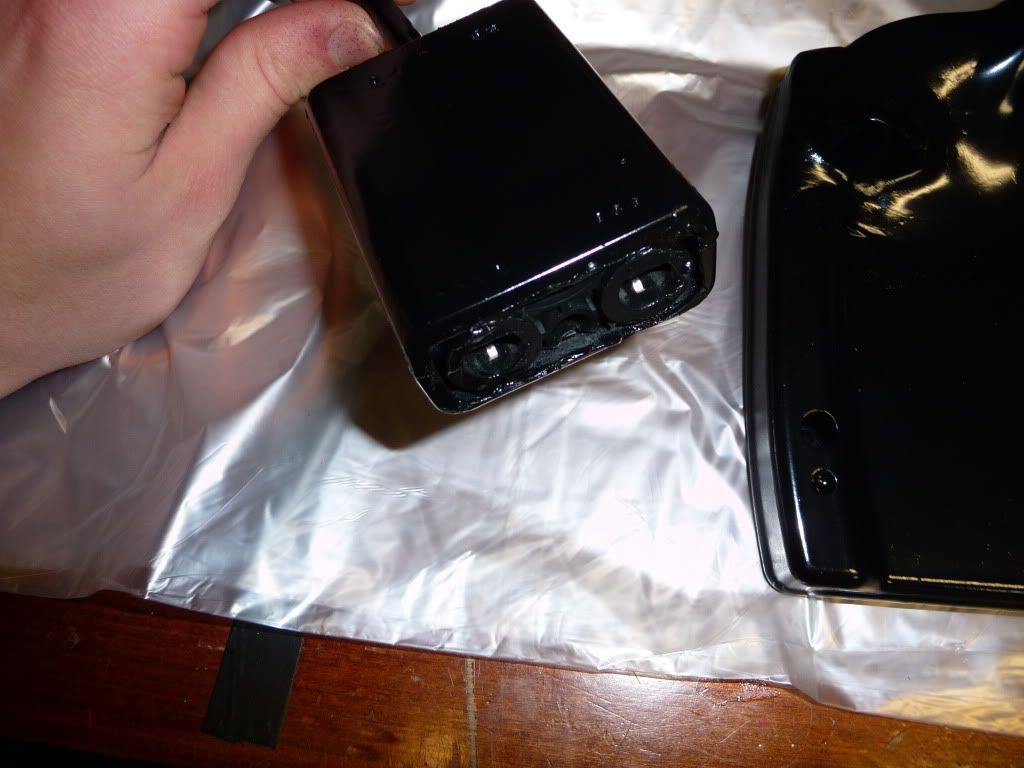
- ZN-40 casing
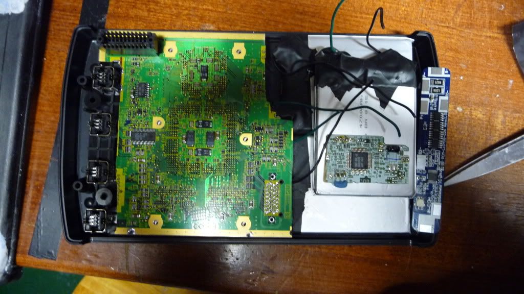
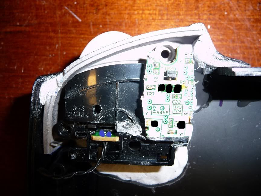
- Rev A board
- Three 3.7v 4700mAh batteryspace batteries (Got them from samjc3
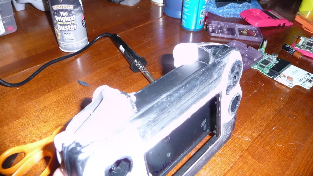
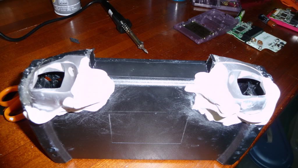
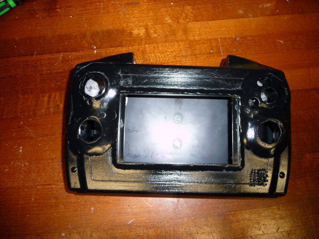
Here is my progress so far (Will be updated)
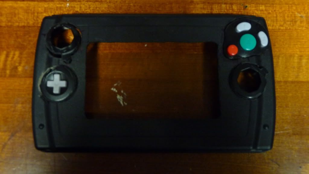
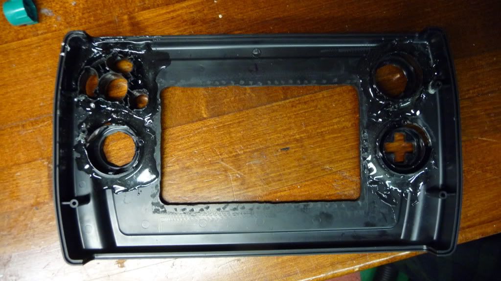
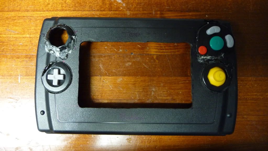
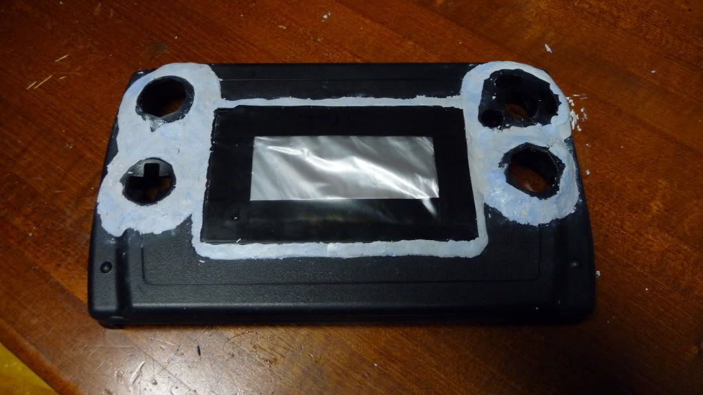
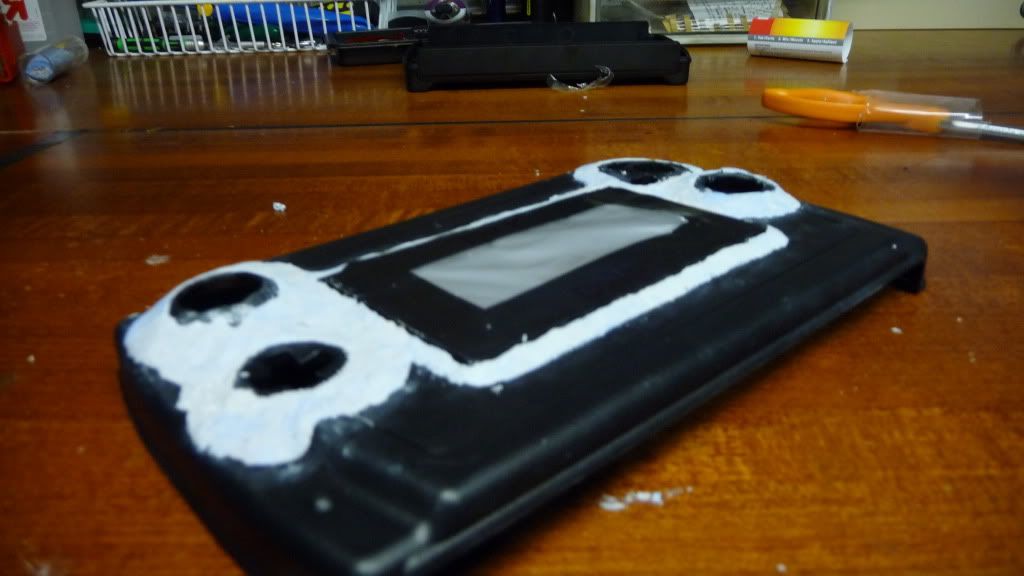
- Drilled screen hole
- Drilled Holes for all the buttons
- Partially trimmed the board
PICS:
 My name is blue_stalfos on MR and MBB