Yeah, I'm probably going to lay it down to shrink the thickness off the final unit if I can't chop enough from the circuit board of the expansion pak. We'll see.
I just want to make sure we all all talking about this? Everyone is just referring to "the previous one" or something like that. :D
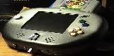
I changed the name of the beast ones more.
E: Arghhh! The postages to Finland are ridiculous. If I can't find any good batteries from here, I'm not going to include them in my work. Another little problem is the voltage regulator for the three point three volt line. I'm not going to cheat TI for free samples. If I buy one from here, postages are atleast five times more than the actual component.
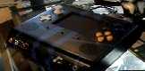
Here you can see thermal grease on the chips. I hot glued the heat sinks on place. I still left the two small ones loose, beacause I need some space to solder the expansion pak which came today!
I just ordered 2 x 2 (means 4 pieces) 2200 mah batteries. I will include two in this which should be enough. Why there's so much cords in those?
Regarding those batteries, the top thicker cord is the actual power, the bottom one is for balancing and charging. You can (somewhat unsafely) ignore that connector. But you may need it for wiring a protection module.
Can I ignore them, if I have charger with the safety circuit and that stuff?
Is there any easy way to make some leds to indicate that batteries are going to be empty soon? It would be frustrating to play couple of hours only to forget to save and lose all data.
Looking good so far except that looks like way too much thermal grease on the chips. You only need a thin layer (just enough to make good contact between the heatsink and the chip). And never, ever use hot glue to mount a heatsink - it will most likely melt all over. I tend to use just a tiny spot of superglue in at least 2 corners of the heatsinks to hold them on and this works well.
Current projects:
Ultimate N64 Guide
N64 Portable (x2)
NES Portable
Neildo_64 wrote:Looking good so far except that looks like way too much thermal grease on the chips. You only need a thin layer (just enough to make good contact between the heatsink and the chip). And never, ever use hot glue to mount a heatsink - it will most likely melt all over. I tend to use just a tiny spot of superglue in at least 2 corners of the heatsinks to hold them on and this works well.
Holy crap! Is that frosting on your chips or what?
Wipe that crap off, clean off the chips with rubbing alcohol and put a small drop on each chip. You hardly need any! The thinner the coating, the better.
Hot glue is just going to melt into a sticky mess the first time you play a game. You need to use some insulated wire to hold it on.
you only need a paper thin layer. only JUST ENOUGH to cover the chip. spread it thin, put the heat sink on, and twist it back and forth a teeny bit to work air bubbles out.
Thanks for advise. I remember someone else using hot glue so I did that also. Well, I'll fix it tomorrow. Super glue doesn't melt down?
Does anyone know, if I can still use brightness control after doing the led mod for PSOne screen? I really want to use leds, because the backlight of the screen drains so much current. It wouldn't matter if I didn't use batteries. I'm going to do the same thing as SifuF did with the volume and brightness controls so I can say goodbye to four additional buttons.
Today I soldered the expansion pak. It really was a pain. Every other wire goes directly on top of the board and every other goes above. I'll put same insulation between them next time, so they can't touch each other. I didn't have time to test this so I'm not sure, if it works. I got it soldered quite nice and clean so it should. I don't recommend doing this, if you don't have a lot of patience. I can post some high resolution pictures, if you want.
Today I soldered the expansion pak. It really was a pain. Every other wire goes directly on top of the board and every other goes above. I'll put same insulation between them next time, so they can't touch each other. I didn't have time to test this so I'm not sure, if it works. I got it soldered quite nice and clean so it should. I don't recommend doing this, if you don't have a lot of patience. I can post some high resolution pictures, if you want.
I would love some high resolution pics. I would relocate the pak if I knew what to solder. I couldn't really understand sifufs guide when it came to knowing where to put everything.
Here's one huge picture. But aknowledge I haven't tested this yet. I still don't recommend this to someone who hasn't soldered quite much. You also need one pretty sharp soldering iron. In worst case you may damage the mother board so bad, it's impossible to solder the wires and get it to work again. Patience!
Liuhuparta wrote:Here's one huge picture. But aknowledge I haven't tested this yet. I still don't recommend this to someone who hasn't soldered quite much. You also need one pretty sharp soldering iron. In worst case you may damage the mother board so bad, it's impossible to solder the wires and get it to work again. Patience!


