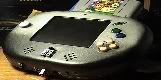
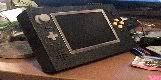
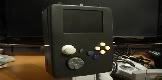
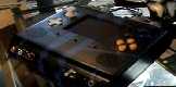
When I saw sifufs n64p, I new I wanted to make an n64p. I knew it wouldn't be as awesome as his but whatever.
You can see he uses a c stick as the c buttons, which proves it can be done.
So does anyone know how to convert a joystick to a digital pad?
I would love to use one, it would save space and be pretty cool too.
How do you use the c stick as the c buttons
Moderator: Moderators
-
BeholdASon
- Posts: 27
- Joined: Wed Jan 14, 2009 7:22 am
This should helpSifuF wrote:Yes. You've got it. That method works with an official N64 controller.Kyo wrote:did you just connect the middle leads of the pots from the C-stick to ground and used the other 4 as a switch (with additional resistors to ground to make it more sensitive) or did you use a more complicated method?
When I originally tried this with the gamecube stick, the resistor values needed were 6k8 ohms. But I just wired up a psx stick (also a 10k pot) which needed resistors of 8k2 ohms. You may need to experiment with values.
However, I was unable to recreate this with the 3rd party pad I'm using. The controller would register a button press with a very small amount of current flow and the 10k pot was too 'narrow' resistance wise, to make a clear on and off. So I had to use the pot as a potential divder with an LED bargraph circuit that would switch the buttons via transistors.
SifuF

I zero credit all it was all StifuF i just done a copy and paste job

Microsoft is making much of its security enhancements, which Ms Barzdukas said makes IE 8 "hands down the most secure browser on the market."
Last edited by Kyo on Sat Feb 06, 2021 6:02 pm, edited 1 time in total.
-
BeholdASon
- Posts: 27
- Joined: Wed Jan 14, 2009 7:22 am
The potentiometers are a long circular resistor with a third wire that slides back and forth around the length of it. So there is always a resistor between the two outside pins, and the middle pin has an adjustable resistance to the other two.
Physically it might look like this:


In this image I stole from wiki, the potentiometer is shown on the right as the resistor with an arrow. The arrow is the adjustable middle pin, if you didnt know already. The equivalent circuit we will be working with is on the right. Because of how it is made, R1 + R2 will always equal the same number, which is the value of the pot. For example it might be 10k. RL just represents the rest of our circuit, and we will assume its value is very high (>100k)
When you turn the pot all the way to the left (top), R1 goes to zero, and R2 goes to the max value, ie 10k. In the middle, R1 = R2 = 5k, and at the bottom, R1 is 10k and R2 is zero.
When you push a button, you take an open circuit (infinty resistance) and close it (almost zero resistance). However you can probably cheat, and if the resistance is "pretty high", like lets say 6k, the button will still be off, and if it is "pretty low", like maybe 1k it would count as on.
Can you see where this is going?
When the stick is centered, so is the pot. when you push it all the way up, you short the middle pin to the top pin and it counts as a button press.
If you use a large enough pot, like 500k, then there should be enough resistance in the neutal position so that all the buttons are off. If you are stuck with a 5 or 10k pot though, you might need an additional series resistor on the middle pin to make it work properly. If its too large though it wont work either. If you go this route I would suggest putting potentiometers (small, semi-adjustable trim pots) so you can play around with it without continually soldering resistors in and out. It might also work as some kind of "sensitivity" adjustment.
Technically for digital buttons this should all be buffered with transistors or something
Physically it might look like this:
In this image I stole from wiki, the potentiometer is shown on the right as the resistor with an arrow. The arrow is the adjustable middle pin, if you didnt know already. The equivalent circuit we will be working with is on the right. Because of how it is made, R1 + R2 will always equal the same number, which is the value of the pot. For example it might be 10k. RL just represents the rest of our circuit, and we will assume its value is very high (>100k)
When you turn the pot all the way to the left (top), R1 goes to zero, and R2 goes to the max value, ie 10k. In the middle, R1 = R2 = 5k, and at the bottom, R1 is 10k and R2 is zero.
When you push a button, you take an open circuit (infinty resistance) and close it (almost zero resistance). However you can probably cheat, and if the resistance is "pretty high", like lets say 6k, the button will still be off, and if it is "pretty low", like maybe 1k it would count as on.
Can you see where this is going?
When the stick is centered, so is the pot. when you push it all the way up, you short the middle pin to the top pin and it counts as a button press.
If you use a large enough pot, like 500k, then there should be enough resistance in the neutal position so that all the buttons are off. If you are stuck with a 5 or 10k pot though, you might need an additional series resistor on the middle pin to make it work properly. If its too large though it wont work either. If you go this route I would suggest putting potentiometers (small, semi-adjustable trim pots) so you can play around with it without continually soldering resistors in and out. It might also work as some kind of "sensitivity" adjustment.
Technically for digital buttons this should all be buffered with transistors or something

"Linux is only free if your time is worthless"
nice little writeup, in case my tutorial has been unclear. You do not connect the outer leads with ground (that makes no sense, you connect the inner leads with ground already.), You connect them to the other side (the chip, the trace, whatever)
Sensitivity has all been explained, but timmeh is right in saying that it would be a good practice to filter this signal with a transistor, however, it is not required.
Sensitivity has all been explained, but timmeh is right in saying that it would be a good practice to filter this signal with a transistor, however, it is not required.
-
thewise1
- Portablizer Extraordinaire
- Posts: 1413
- Joined: Sun Jan 04, 2009 8:18 pm
- Location: Sitting on my pile of authentic minnesota dirt
I thought that's what I asked before and you guys said that it was wrong, then I guess I was right. But you're guide did help to get that answer. I guess I did understand it correctly. Thanks guysKyo wrote:well, is my tutorial unclear? connect the middle leads with ground, the other ones with the directions