I cant get video to my psone screen from the snes board. I can get left and right audio from the speakers, but not video. I know the wires are hooked up right. the only problem is, is that i used to much heat and now i cant solder anything to the psone video output. i also tried both pin 1 on either side of the pins, but i still get nothing.
Please help me im trying to figure out other alternate sources of video output, or if you have an idea please help me.
I NEED HELP WITH MY SNESP!!!!!
Moderator: Moderators
-
TwiliChaos
- Posts: 6
- Joined: Sat Dec 27, 2008 2:10 am
i am using a mini snes. i am new at this, since this is my first portable. I bought bens book how to hack portables, and i did everything up to this part. i already modded the psone screen with L.E.Ds, and i was able to get audio.
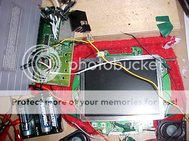
if you cant see that too well, then i will tell you whats connected to what.
1) i have a wire going from the 7805 regulator to the positive lead of my battery.
2) i have one wire going from the 7805 regulator to the ground of the snes ( spot 2 ). I then have another lead coming from spot 2 of the snes, going to the ground on the psone screen. ( left of the screen)
3)i have one wire coming from the snes board spot 3, to spot 3 on the regulator.
4) i have all the negative leads for the LEDs grounded on the psone board.
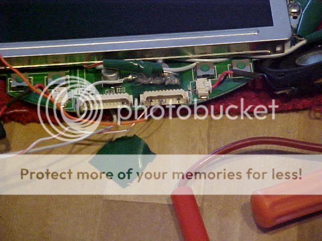
5)I have a lead coming from the video spot on the snes, going to pin 1 on the smallest connector in the front. i also have a ground from pin 4 to the ground on the psone screen.
6) i have a lead coming up from the +5 volts of the psone screen, but didnt connect it to anything, because i have no clue whats going on and the book is confusing. I did not turn the screen on now because i am not sure about it. so please reply ASAP with answers.
if you cant see that too well, then i will tell you whats connected to what.
1) i have a wire going from the 7805 regulator to the positive lead of my battery.
2) i have one wire going from the 7805 regulator to the ground of the snes ( spot 2 ). I then have another lead coming from spot 2 of the snes, going to the ground on the psone screen. ( left of the screen)
3)i have one wire coming from the snes board spot 3, to spot 3 on the regulator.
4) i have all the negative leads for the LEDs grounded on the psone board.
5)I have a lead coming from the video spot on the snes, going to pin 1 on the smallest connector in the front. i also have a ground from pin 4 to the ground on the psone screen.
6) i have a lead coming up from the +5 volts of the psone screen, but didnt connect it to anything, because i have no clue whats going on and the book is confusing. I did not turn the screen on now because i am not sure about it. so please reply ASAP with answers.
-
Kurt_
- Portablizer
- Posts: 5748
- Joined: Thu Nov 24, 2005 10:32 am
- Steam ID: kurbert
- Location: Ontario, Canada
- Contact:
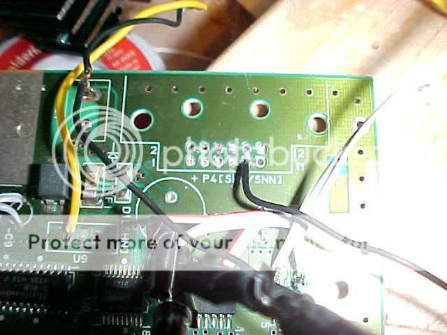
Mini SNES, first picture. Black wire on the right.
It looks like it's bridging two pins, and I'm pretty sure that's your video wire, is it not?
Also, the mini SNES CAN output RGB easily. Well, I say easily because no modifications are necessary. However, you do need to solder 4 wires to a surface-mount IC. The information is in a link to another site somewhere in this forum. (My bad, I found it in the screen hacking forum sticky)
http://www.gamesx.com/rgbadd/snes2rgb.htm
Ignore the small amplification circuit he built, for a portable where the wires are no longer than 6 inches, it's really not necessary.
RED: 20
GREEN: 22
BLUE: 24
C-SYNC: ? (They removed it because they thought it was faulty information)
(Don't forget +5V to pin 12 of the PSOne screen if you're doing RGB)
(Stumbled across this, looks to be useful and well done: http://members.optusnet.com.au/eviltim/ ... t.htm#snes)
Hey, sup?
this is sort of confusing..... is there anyway you can get like a diagram for me. i understand that you are saying my black wire coming from the regulator to the ground of the snes to the ground of the psone screen is bad? how should i go on fixing this problem. sorry that im asking you for all this but this is my first portable.
-
Kurt_
- Portablizer
- Posts: 5748
- Joined: Thu Nov 24, 2005 10:32 am
- Steam ID: kurbert
- Location: Ontario, Canada
- Contact:
Capitals makes us want to answer better! 
Look kid, it's not wired right. You thinking that it is correct is the problem. Sure, the wires *MIGHT* all be soldered to the correct contacts, but it's also possible they're accidentally connected to contacts beside those which you did not intend to solder to.
---------------
I actually see the problem now. It's quite obvious. Everyone, start from the beginning and work your way down. Can you spot the problem too?
I'll post the answer later tonight.
Hey, sup?