Bacteria's project - PSone portable: IntoPlay finished: PICS
Moderator: Moderators
-
bacteria
- Portablizer Extraordinaire
- Posts: 3984
- Joined: Fri Apr 20, 2007 12:14 am
- Location: Hampshire, UK
- Contact:
Didn't get much done today unfortunately; what I did do was to desolder the joystick from the board, hot glue it to a piece of perspex (less height that way) and make two bits of perspex sticking out of the underside to clip into the perspex around the case to keep it in place.
Spraypainting the joystick caps didn't prove effective, after rubbing for a while it started to come off, so used some enamel paint instead. If that fails, will have to have the joysticks stock grey instead of black.


Middle pic was before the joystick cap was painted with enamel paint - had to trim a little more off the edge of the joystick cap, as per pic. Going to use a varnish to preserve the paint, then secure the joystick assembly in place (tomorrow).
Spraypainting the joystick caps didn't prove effective, after rubbing for a while it started to come off, so used some enamel paint instead. If that fails, will have to have the joysticks stock grey instead of black.
Middle pic was before the joystick cap was painted with enamel paint - had to trim a little more off the edge of the joystick cap, as per pic. Going to use a varnish to preserve the paint, then secure the joystick assembly in place (tomorrow).

-
Basement_Modder
- Portablizer
- Posts: 962
- Joined: Sun Aug 24, 2008 7:16 am
- Location: Next door to my neighbor
- Contact:
-
bacteria
- Portablizer Extraordinaire
- Posts: 3984
- Joined: Fri Apr 20, 2007 12:14 am
- Location: Hampshire, UK
- Contact:
Managed to get some project work done this morning; however I spent a lot of time fine sanding the 4 buttons (due to the spray paint residues making the holes very slightly bigger) - look very nice in case. Hacked the 4 button part of the controller mobo and screwed it in place to the base. Spent a bit more time on the joystick, to get it in place; nearly there with it.
Took pics but no chance to upload them yet. Won't have much project time until early January, but will snatch a bit of time here and there, so might be able to get some updates done in meantime.
Took pics but no chance to upload them yet. Won't have much project time until early January, but will snatch a bit of time here and there, so might be able to get some updates done in meantime.
-
hailrazer
- Portablizer Extraordinaire
- Posts: 2764
- Joined: Mon Jul 10, 2006 8:57 pm
- Location: Georgia Sweet Georgia
LOL......Yea I had a bunch of hole sanding to do on my portables.bacteria wrote:Managed to get some project work done this morning; however I spent a lot of time fine sanding the 4 buttons (due to the spray paint residues making the holes very slightly bigger) - look very nice in case.
Note to self.....Drills holes slightly bigger before putting on 8 coats of paint.
My Portable Systems:

-----Genimini---------Darth64---------Dreamtrooper--------Ncube---------Kamikazi64---N64Boy Advance
-----Genimini---------Darth64---------Dreamtrooper--------Ncube---------Kamikazi64---N64Boy Advance
-
bacteria
- Portablizer Extraordinaire
- Posts: 3984
- Joined: Fri Apr 20, 2007 12:14 am
- Location: Hampshire, UK
- Contact:
(When I have queries, I tend to use the search feature and see if the answers are in the archive): In 2005, Gamelver attempted to remove big chunks from his PSone screen and posted a pic of his hacked board, against an unhacked one:

Forum link
It looks like he might have trimmed off a bit too much as the topic died, presumably for that reason, as he had promised to post documentation if successful. He certainly took a lot of board off, and looking at the PSone screen, looks like a few components went (which might have been the straw that broke the camel's back).
There doesn't appear to be anyone else on the forum who has tried it....Until now!!!
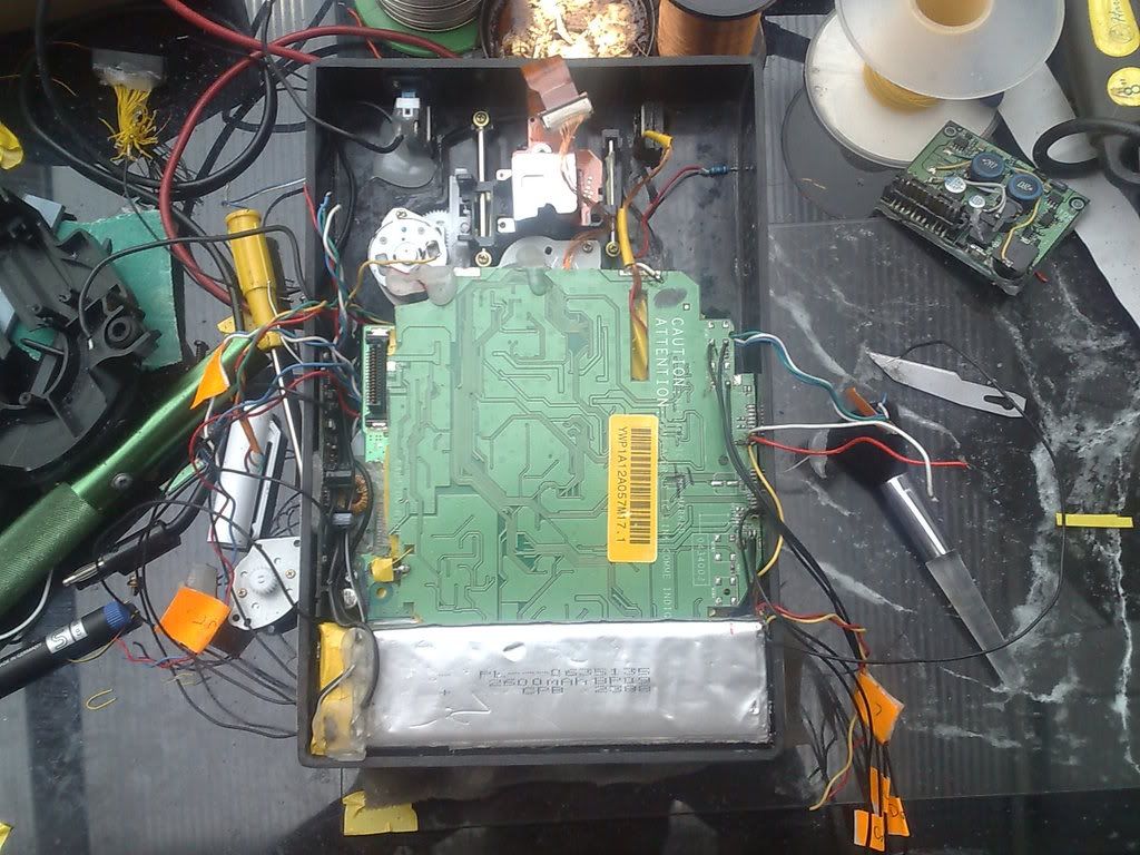
I made a *slight* miscalculation with my measurements for one part of the case, I thought I had allowed the height of the case to be enough to just take of some of the empty board by the transformer and not use the plugs at the bottom of the PSone screen mobo, or maybe trim some of the plastic plugs down a little. I then thought I just needed to relocate the transformer as I needed to trim off some of the top of the board; it actually transpires that, on the positive, I won't need to play with the transformer, maybe just take off some of the unused board at the very top: on the negative, I will need to trim off more of the bottom of the board. I think I can get away with leaving the solder points to the two PSone plugs, which would be convenient; (about 6mm from the bottom) although, looking at the board I can trim off up to nearly 8mm from the bottom before I start getting issues with having components in the way.
This actually is no big deal. The traces are easy to follow and not too hard to tap onto if needed; however, if I can keep the pins intact for the plugs, I can just solder to these points no differently to before, just remove some of the unneeded mobo.
After doing the joysticks, I will hack the screen mobo as mentioned. Look forward to this!
Forum link
It looks like he might have trimmed off a bit too much as the topic died, presumably for that reason, as he had promised to post documentation if successful. He certainly took a lot of board off, and looking at the PSone screen, looks like a few components went (which might have been the straw that broke the camel's back).
There doesn't appear to be anyone else on the forum who has tried it....Until now!!!
I made a *slight* miscalculation with my measurements for one part of the case, I thought I had allowed the height of the case to be enough to just take of some of the empty board by the transformer and not use the plugs at the bottom of the PSone screen mobo, or maybe trim some of the plastic plugs down a little. I then thought I just needed to relocate the transformer as I needed to trim off some of the top of the board; it actually transpires that, on the positive, I won't need to play with the transformer, maybe just take off some of the unused board at the very top: on the negative, I will need to trim off more of the bottom of the board. I think I can get away with leaving the solder points to the two PSone plugs, which would be convenient; (about 6mm from the bottom) although, looking at the board I can trim off up to nearly 8mm from the bottom before I start getting issues with having components in the way.
This actually is no big deal. The traces are easy to follow and not too hard to tap onto if needed; however, if I can keep the pins intact for the plugs, I can just solder to these points no differently to before, just remove some of the unneeded mobo.
After doing the joysticks, I will hack the screen mobo as mentioned. Look forward to this!
bacteria, you are not quite right. While it's not done to that extent very often, it is a fairly common practice to remove the top (containing the transformer) - so yes, that's safe. If you look at techknott's GCp thread, you'll see that he too hacked the PSOne screen smaller.
http://forums.benheck.com/viewtopic.php ... &start=105
So yeah, if you follow his lead, you'll be able to make it really small.
http://forums.benheck.com/viewtopic.php ... &start=105
So yeah, if you follow his lead, you'll be able to make it really small.

-
bacteria
- Portablizer Extraordinaire
- Posts: 3984
- Joined: Fri Apr 20, 2007 12:14 am
- Location: Hampshire, UK
- Contact:
Actually, i'm really pleased i'm not the first to do this as it proves the theory works as it should. That's why I did some research to see what others did to solve this problem, but didn't see his thread. On this occasion, I didn't want to be the first! That has given me more confidence all is fine - his cut points at the bottom of the screen are about where I need to make them too! For a couple of minutes last night I thought, "oh crap, won't fit", but it will with some cutting and will be absolutely fine!
Might be common to cut the top, Kyo, but that isn't my issue. BTW - it will be nice when you can cast your "expert" views you have these days into making your own systems! - I look forward to seeing your work.
Neildo_64 - Excellent, nice job.
Got the joystick in place, re-did it. It is now neat, held in by two screws, removable and works really well. No time to post pics today...
Might be common to cut the top, Kyo, but that isn't my issue. BTW - it will be nice when you can cast your "expert" views you have these days into making your own systems!
Neildo_64 - Excellent, nice job.
Got the joystick in place, re-did it. It is now neat, held in by two screws, removable and works really well. No time to post pics today...
-
bacteria
- Portablizer Extraordinaire
- Posts: 3984
- Joined: Fri Apr 20, 2007 12:14 am
- Location: Hampshire, UK
- Contact:
Ok, the update mentioned before:
One thing I noticed was that opening up different controllers, even the same type, can mean different boards, so you will need to take the pics of the boards I use as general info as yours might be slightly different - same principles and methods though to mod them.
For example, one of the cut 4 button pads, removed from the controller mobo, looks like this:

and another one like this (which I am using):

...with the rubber contact pad on:

Here is the pinout - what connects to what. I tend to use white wires for common (ground) wiring.

A little flux from a pen applied, then solder - solder sticks, allowing for soldering wires too. Make sure you use a multimeter to make sure no connections touch any others!
Done, wires stuck with hot glue, onto a piece of card, so they don't move about.

Had to trim off some of the perspex surround so I could get the leftmost button in

4 button pad in place, screwed in place in the center (as designed in the controller originally). Screwing in place makes it easy to remove if needed and also neater.

You can use rubber tact switches, contact pads from whatever else lying about from old controllers, you have choices.
Wired up the joystick, and the shoulder button contacts

Then cut a piece of perspex, hot glued it to the joystick; and the two screws hold the assembly in place. The advantage of this is that it is easy to remove the assembly if needed and also the joystick isn't relying on flexing hot glue for strength, rather rigid perspex. This is especially important as there is nearly no tolerance for error. The line between the two screws follows roughly the center of the joystick, which means even pressure when joystick is used.

The joystick is central to the hole, moves freely and doesn't catch when being turned; so release the joystick and it springs to central position, as it should do. That took a lot of work to achieve!
Not showing pics of the front of my system until project is finished, for maximum impact...
One thing I noticed was that opening up different controllers, even the same type, can mean different boards, so you will need to take the pics of the boards I use as general info as yours might be slightly different - same principles and methods though to mod them.
For example, one of the cut 4 button pads, removed from the controller mobo, looks like this:
and another one like this (which I am using):
...with the rubber contact pad on:
Here is the pinout - what connects to what. I tend to use white wires for common (ground) wiring.
A little flux from a pen applied, then solder - solder sticks, allowing for soldering wires too. Make sure you use a multimeter to make sure no connections touch any others!
Done, wires stuck with hot glue, onto a piece of card, so they don't move about.
Had to trim off some of the perspex surround so I could get the leftmost button in
4 button pad in place, screwed in place in the center (as designed in the controller originally). Screwing in place makes it easy to remove if needed and also neater.
You can use rubber tact switches, contact pads from whatever else lying about from old controllers, you have choices.
Wired up the joystick, and the shoulder button contacts
Then cut a piece of perspex, hot glued it to the joystick; and the two screws hold the assembly in place. The advantage of this is that it is easy to remove the assembly if needed and also the joystick isn't relying on flexing hot glue for strength, rather rigid perspex. This is especially important as there is nearly no tolerance for error. The line between the two screws follows roughly the center of the joystick, which means even pressure when joystick is used.
The joystick is central to the hole, moves freely and doesn't catch when being turned; so release the joystick and it springs to central position, as it should do. That took a lot of work to achieve!
Not showing pics of the front of my system until project is finished, for maximum impact...
-
Sun-Wukong
- Posts: 225
- Joined: Tue Aug 26, 2008 4:58 pm
Can't wait! Any ideas on what game you'll use to show it off? I vote Metal Gear Solid.bacteria wrote:Not showing pics of the front of my system until project is finished, for maximum impact...
Chapel wrote:Ah shucks, I was really hoping to make an SNES encased in a 19 pound glob of hotglue and duct tape.