Controler stupidity

Includes but not limited to: SNES, Genesis, Sega CD, PlayStation 1, Nintendo 64, Dreamcast, Game Gear and I guess the Virtual Boy.

Moderator: Moderators

Post Reply
Droke
Posts: 72
Joined: Sat Oct 07, 2006 9:57 pm

Controler stupidity

Post by Droke »

My friend has a genesis he bought at a yard sale for $3, one problem it has is that the control wires were crushed. Well, I was fixing them for him and unsoldered the wires going into the ciruit board... ...but forgot to mark which went where...

I need help finding what goes where again, I'ver traced all but 4 wires useing his second controler of a differnt internal wireing. The four go directly into the IC so I cant tell which goes where.

Here is a *blurry* pic of what I have, if anyone else has the same model could you tell me which goes where? (More then anything else the pic is to allow you to see if your model is the same)

Image
jedi knight
Posts: 644
Joined: Sun Jan 22, 2006 3:05 pm

Post by jedi knight »

I am pretty sure I have that model. Let me go check...
edit: No dice. Sorry.
Meh, I don't post much.
sammy
Posts: 568
Joined: Thu Dec 08, 2005 3:13 pm

Post by sammy »

You need http://pinouts.ru/Game/genesiscontroller_pinout.shtml
and the pinouts of the ic. I haven't got a link up but someone should.
Skyone
Moderator
Posts: 6390
Joined: Tue Nov 29, 2005 8:35 pm
Location: it is a mystery
Contact:

Post by Skyone »

See how the pins are numbered? It looks like you've figured that Pin 1 is red, right?

From the sticky:
Skyone wrote:Controller Data (3 Button Controller)

Pin 1 = Brown = Up
Pin 2 = Red = Down
Pin 3 = Orange = Ground/Left
Pin 4 = Yellow = Ground/Right
Pin 5 = Green = 5v
Pin 6 = Blue = Button A/Button B
Pin 7 = Gray = Select
Pin 8 = Black = Ground
Pin 9 = White = Start/Button C

Image
9 pin D-SUB female connector at the controller

Image
9 pin D-SUB male connector at the Genesis

Research by Skyone
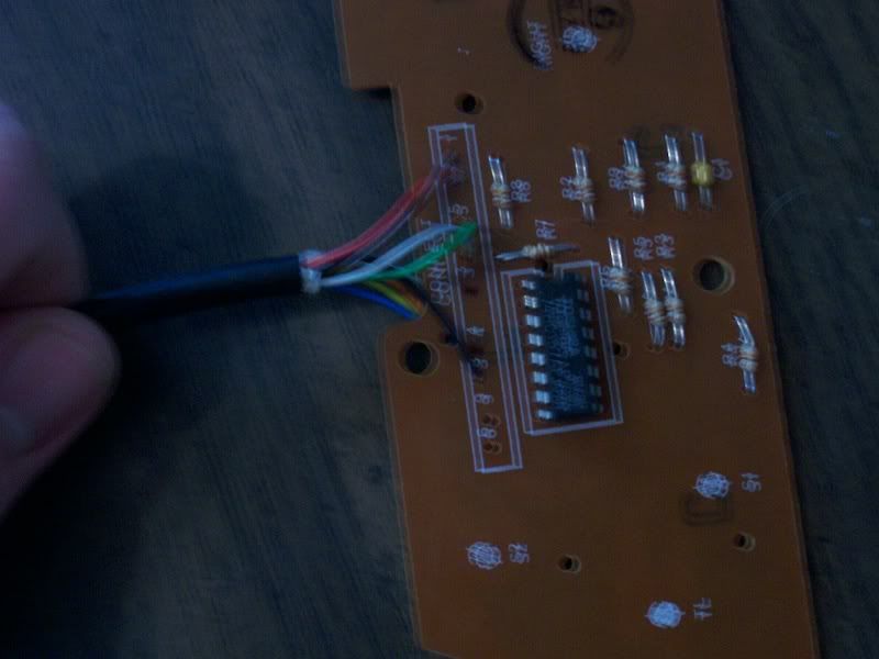
Luckily, Sega made it easy on us because they made the pin numbers of the colored wires the same pins of the connector. As you can see, on the PCB where the colored wires go in, the numbering goes:

1, 2, 5, 7, 3, 4, 8, 9, 6

Refer to the above pin -> color diagram above.

1. Brown
2. Red
5. Green
7. Gray
3. Orange
4. Yellow
8. Black
9. White
6. Blue

:) Tell me if you do not understand.

-Skyler
Droke
Posts: 72
Joined: Sat Oct 07, 2006 9:57 pm

Post by Droke »

I think I do, I'll look further when I can actualy do something. :)
CronoTriggerfan
Moderator
Posts: 4131
Joined: Fri Jan 27, 2006 3:07 pm
Location: University of Michigan - Ann Arbor
Contact:

Post by CronoTriggerfan »

And if that stuff still doesn't do the job, here's a nice compilation on the controller pinouts, color coded, and including the controller IC itself. Gamesx is a cool site as it is, I'd bookmark it. A/V and controller pinouts for almost every system imaginable, plus a ton of mods on how to get different video signals out of each console. Good luck! :)

CTFan
Image
Post Reply