Please tell me how to
make an Atari portable Step-by-Step?

The simplest VCS to make into a portable and the one we'll be covering is the Atari VCS 2600 4-Switch. This is the unit with 4 silver switches in front, a cartridge slot in the middle, and the difficulty switches and joystick ports on the back. It has 1 PCB inside. This is the most common type of Atari, as it was built during the heyday of the company. This is the type that has been used on all of my portable VCSp's thus far. You'll need to have an Atari like this one to use this guide.
(Note: Do not confuse a 4-Switch with the Atari 2600 Junior. The Junior is smaller, flatter and has brushed aluminum on it. The Junior cannot be chopped apart using this guide)
The Tools:
I would recommend that you have the following handy before starting out on your quest:
-
Soldering iron, 15 watt preferred (more precise)
-
Desoldering iron, to remove parts and fix screw-ups (not saying you WILL, but... you COULD!)
-
Multimeter for testing voltages and resistance. You can get a cheap one for $10 at Wal-Mart. Finding out if and where voltages are will save you a lot of time. Also they're great for debugging.
-
Useless old floppy & hard drive cables from old crappy computers. Computer places will usually GIVE this stuff away and it's great for roll-your-own ribbon cable. Just peel like string cheese and use as needed!
-
Screwdrivers, snippers and wire strippers. In lieu of wire strippers you can of course use your teeth (as I do) but remember, it is no substitute for proper brushing.
-
A PAIR OF TWEEZERS. Get a decent pair, maybe rubberized with a nice grip. The makeup section of a store usually has a good selection. It's worth it for soldering and holding small wires. Also you can grind down the tips to make them more accurate.
-
A hot glue gun. Words cannot express how useful these are.
The Steps:
1) Opening your Atari VCS and hacking it into a 4" x 4" Square
2) Wiring it so it keeps working
3) Getting composite video and audio off the board
4) Attaching joysticks, buttons and paddles
5) Finding & using a suitable screen
6) Building a case
Step 1:
Opening your Atari VCS and hacking it into a 4" x 4" Square
Opening your Atari VCS
On the bottom of your Atari you will find 4 screw holes. Unscrew them all using a Philips and then throw them away, you'll never need them again. (if you're building a portable unit) They'd just get lost in your junk drawer anyway. Pull the two halves of the unit apart.
You'll see one circuit board with thin plating in the middle and switches on each side. Note the little twisted (cheap) metal tabs holding the armor shielding on. Un-twist these with a needle nose pliers. You should then be able to pull the two halves apart (from above and below the board) and remove the plating.
Hacking the board into a 4" x 4" Square
Here is a front/back diagram of where to cut:
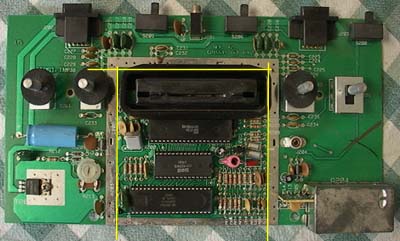
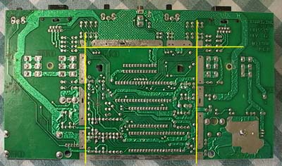
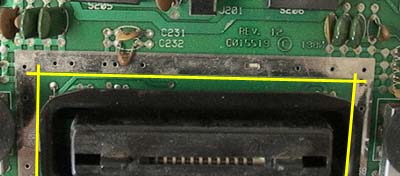
All slices are just inside the metal square, except for the bottom part of the metal square which is left intact.
Now, you can use a band saw if you want, but it's actually almost easier (and we don't all have band saws) to use a utility knife and SCRAPE the PCB along the cut-lines. Scrape along each cut-line on both sides two or three times deeply and with lots of pressure. You can then bend the board and it should snap cleanly along those lines, much like scoring glass. Kids - ask an adult for help with this part!
NOTE: Even though it may seem easier to pull the knife TOWARDS you as you do this, try moving the knife OUTWARD instead. I cannot be responsible for any injury if you don't handle the knife properly, and besides, if you gash yourself and go to the hospital BEFORE you finish your portable Atari, what are you gonna do while waiting in the emergency room?
After hacking the board, check the loose ends of the traces along the cut (especially the ones that led to the joystick ports) Make sure they haven't bent or touched each other, otherwise your controls won't work right. You can use an X-Acto knife to trim them if need be.
Keep the parts of the board you've cut off, there are things you may need... (more later)
Step 2:
Wiring it so it keeps working
Choosing a battery & making a power supply
The Atari motherboard is not exactly a cutting-edge piece of technology, therefore it sucks power. Usually around 200mA, but once you add on all the wiring and a screen it gets up around 600-700mA pretty easy. So you need a battery than can handle that and still run for a decent amount of time.
Also when selecting a battery the power regulator that you're using must be considered. The easiest one to use is a 7805 regulator, which is already what's inside your Atari (or NES, or SNES...) but you should buy a new one at Radio Shack (part #276-1770) to use for your project.
All voltage mentioned in this article is DC (direct current, like a battery)
The 7805 is a linear regulator that takes a voltage source and knocks it down to 5 volts. Any extra voltage above that is turned into heat, so you should get a small heat sink at Radio Shack and attach that to the 7805. The 7805 drops out, or stops working, when the input voltage gets lower than 7 volts, so your battery needs to be at least 7 volts or higher. Between 7 and 9 is good, I use a Sony camera battery and it is 7.2v.
This drawing shows where to attach your battery and Atari to the 7805. Your unit's "power on" switch should be between the battery + and the 7805's unregulated input. It's a good idea to hook up the battery to the 7805, switch it on and make sure +5v is coming out of the regulated pin BEFORE you hook it to your Atari. If you put more than 5v into your Atari IT WILL DIE.
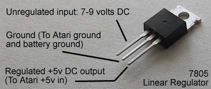
The battery, regulator and heat sink will be your power supply. From this point on, if the project calls for +5v it will come from the regulated output pin of the 7805. If the project calls for Ground, it will go to the middle ground pin of the 7805.
Re-wiring the board
The back of the 4" x 4" board should look like this:
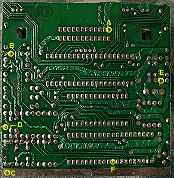
Only a few positive and negative traces are actually severed when hacking the board, and we'll bypass them here:
Connect your +5 volts to spot "E". Then, connect point "E" to point "D". This supplies power to the board.
Again, as boards differ the location of "E" can differ. Look for the big fat trace that went under the RF sheld and towards the big capacitor. That's +5 volts.
Ground needs to be connected. Connect a wire from the 7805's ground pin to the metal strip running along the bottom of the board. This strip will be your "master ground", so you can attach any other grounds to it easily. Next, connect point "C" to point "B", then point "B" to point "A". All grounds to run the board have now been connected.
The Atari will now run, however you won't be seeing any picture.
NOTE: On some motherboards (about 1 in 5) you'll find this little IC (black), a capacitor and resistor (yellow) in the upper right-hand corner.

If you don't see them, go ahead and skip down to Step 3. If the bugger IS there, you will need to remove it and the 2 components next to it and re-wire them your 4" square Atari board... Otherwise the thing will run

Here is the IC, resistor and capacitor from the back of the board (solder side). The thin green line indicates where you can safely "cut out" this section of the board. Or you could desolder the parts and re-wire them on a bit of PC board. Whichever you do, it's a small bit of PCB that is separate from your 4" x 4" square and connected with 3 wires. You could hot-glue it onto the square someplace, whatever fits your fancy.
Either way, the drawing shows what to hook up to the pins. The pin marked "To Mainboard" goes down and follows alongside the Select & Reset traces. It usually ends up at the following location on the back of the left side of the 4" x 4" square:

Again, you can visually follow the trace coming off the IC to verify what it needs to connect to. At this point, the Annoying IC, as I like to call it, is re-connected and you're ready to continue!
Step 3:
Getting composite video and audio off the board.
Making the composite video output mod
First you're need to rewire the color delay potentiometer. Once reconnected, it lets you adjust the 'tint' of the picture. (more on that later) You'll find it on the left side of the board you chopped it. It looks like this: (Note: You can also use a 500k potentiometer)

Desolder it, or remove it any way you can. Next, it needs to be wired to the Atari board. Connect "A" on the potentiometer to spot "F" on the Atari board (see above board photo). Connect "B" to the Atari's ground. Finally, connect "C" to the UNREGULATED input pin of the 7805 regulator - NOT the regulated 5v output. (WARNING: This is the only thing connected to the Atari that should go to the unregulated power)
Now you'll need (2) 1k potentiometers (Radio Shack part #271-280) and (1) 22-ohm resistor (Radio Shack part #271-1103).

In the lower-left corner of the back of your hacked board, you will find the connection for Chroma "C" and Audio "A". Connect a wire to Audio "A", this will get you sound (that needs to be amplified). Connect Chroma "C" to the spot above marked Sync "S". Sync "S" is connected to Pin 2 of the Stella chip, as seen below:

The TIA chip, AKA "Stella" produces the display. Connect some wires to pins 2, 5, 7 & 8. Wire them as such:

or, the non-schematic version that looks like the parts:

Now the Atari can output composite video and audio. (Use the Atari's ground for ground) Using your power supply, hook up the Atari, plug in a game and see if it runs. You can hook the audio and video off the Atari to standard RCA cables and attach them to a TV to test (Note: doesn't seem to work with Sony Wegas or PSOne screens) If nothing shows up, go back up and check the steps. If it works, you can proceed with the controls.
Step 4:
Attaching joysticks, buttons and paddles
Making and attaching joysticks & switches
The Atari joystick is very simple. It's just 5 switches (up/down/left/right & trigger) than when pressed, go to ground (or "pull the pin low"). Here is an example of a basic joystick layout that would work.

The important thing is where to hook the connections. The following drawing displays where:

Each pin needs to go to a switch, what kind is your choice, which then switches to ground when pressed. The P1 and P2 difficulty are EASY when going to ground and HARD when open.
Connecting/making paddles (It's not just for canoe aficionados anymore!)
This requires a few extra components. For each paddle, you'll need a 1 meg-ohm potentiometer (Radio Shack part #271-211) and a .068uf capacitor. The capacitor can be taken from the hack-off Atari board, they're near the joystick ports and look like this:
 (Warning: Do not mistake for Chicklet and eat)
The 1 meg-ohm potentiometer is the paddle. Wire it to the Atari board as shown:

With the switches, controls and paddles set, it's time to think about a screen.
Step 5:
Finding & Using a Suitable Screen
Finding a Screen
Just about any pocket TV that has an Audio/Video input jack should work with your hacked up Atari. The only portable screen I have found NOT to work with the Atari is the 5" PSOne screen, which is too bad because it's pretty cheap these days and BIG!
Here is a list of TFT active matrix screens that I have found to work with this Atari video circuit:
Casio EV-550, 2.5" TFT Screen
(VCSp Rev 1-3)
Casio EV-670, 3" TFT Screen (VCSp Rev 6)
Casio EV-4500, 4" TFT Screen (VCSp Gold)
RCA L2501, 2.5" TFT Screen (Much higher pixel
count that any of the aforementioned Casios) (VCSp Rev 4 & 5)
There are some cheaper passive matrix screens that will work, such as the sub-$75 RCA models at Radio Shack. However, aside from the obvious drawback of reduced picture quality, they are also compatible with fewer games.
I would recommend wiring your Atari with the video circuit and then plugging that into the pocket TV's A/V input jack before you hack up the TV. That way, if it doesn't work, you can return the TV and try again! (just don't tell the clerk you visited this site!)
Wiring the Screen
Typically the TV will have battery terminals and a DC power input jack. Most TV's that run off 3 or 4 AA's will take 5 volts as input. Typically you can get this 5 volts from the 7805 regulator powering the Atari. Attach the 5 volts and ground to the DC power input jack on the TV (not the battery prongs). By looking at the TV's case, you can see which pins are which on the power input jack (if center pin is positive or vice-versa). As TV's vary, please take the time to note where the power inputs to avoid frying the TV.
Once the power is connected, switch the TV to ON so that when the main power is switch ON the TV will come on. (That's possibly one of the most redundant sentences I have ever typed.)
Next, we need to get the video and audio signals into the TV. The audio/video input jack typically looks like the following: (shown removed from TV)

This jack contains 2 things. The audio/video prongs (which connect to a standard stereo 1/8" mini-jack) and the disconnect switch consisting of a single pole with 2 terminals. If a jack is inserted, the center pole connects to the bottom terminal. If no jack is inserted, it connects to the top. On the TV, this is used to disconnect the channel receiver when you plug in an external a/v source. Therefore, if you don't actually plug a jack in, you'll need to solder the connections together so the TV THINKS a plug is in.
On my VCSp's, I use the TV's A/V jack as my A/V OUTPUT jack. (as shown above) In those, I run the TV's +5v though the jack's switch, to the normally closed poles (TV is ON). If a person inserts a jack (meaning they want to play on a big TV), it breaks the circuit and turns off the VCSp's screen.
On the above picture, you can see where the video and audio were connected to the jack. Typically there's 4 pins and then a ground. The outer 2 pins are A/V. Wire the audio and video wires coming from the Atari to those spots on the TV's board and you should be connected. But on the TV side which pin is audio and which is video? You have a 50/50 chance of getting it right, which in electronics means it WILL be wrong the first time you try, so solder it, then unsolder it and switch it around before you even test it (Murphy's Law)
As this may vary from TV to TV, experimentation is suggested. However, every pocket TV with A/V that I've seen thus far works this way.
Converting to White LED's
A typical 2.5" TFT pocket TV will consume 500mA at 6 volts DC. Once you add on the Atari guts and wiring, that's a pretty hungry portable. About 250mA can be saved by converting the TV to use white LED's. This is done by removing the TV's bulb and inverter (or just removing the bulb and disabling the inverter)
WARNING: This is what I would call a 'hard-core' step that could result in your TV buying the farm. If you're confident, and really want to save 250mA, then go for it. If you're a bit worried about damaging your TV, then it's not a big deal to skip it because saving 250mA isn't worth wasting a $150 screen.
You'll need (2) 3 mm white LED's from www.digikey.com, part #CMD204UWC-ND. Digikey rocks, but there's a service charge unless you order $25 worth of stuff, so I'd suggest getting some tact switches and regulators while you're there.
Also, grab (2) 10 ohm resistors (Radio Shack part #271-1101).
The basic concept is to locate the bulb on the screen. It's usually at the base of the screen, running the length with a lead on either end. It's much like a tiny fluorescent lamp. Start by snipping off the wire leads on both ends of the bulb. (This alone should disable the inverter circuit) Then, carefully, and I mean CAREFULLY, snake the bulb out. It's usually held in by 2 small blobs of glue. The bulb will shatter if you bend it too much. If you're really adventurous, you can remove the LCD glass and all the layers of film below it (don't get them dirty or touch the centers) This will give you better access to remove the bulb.

Once the bulb is out, put the LCD screen back in if needed. Then, stick a white LED in each end of where the bulb was. This simulates the bulb. Use hot glue to secure the bulbs in place.
Disconnecting the bulb should stop the inverter from sucking power, but if you can locate and isolate the inverter, you can cut it off completely to save room (as I do with the VCSp Rev 6's). Many pocket TV's, such as the EV-670 shown above have the inverter circuit very near and usually attached to the screen. It plugs into the TV's board. In this case, the channel up/down buttons are attached as well. You'll be looking for a small transformer and a couple surface mount regulators that lead to the screen's bulb. This typically makes up the inverter.
The inverter will typically have +5 volts and ground going to it. Using your multimeter, turn on the TV and determine where the +5 volts and ground come in at. (Note: DON'T touch the prongs that went to the bulb, as they can shock you!) Disconnect the +5 volts and the ground so they cannot reach the inverter. This should disable the inverter once and for all! Next, where the 5 volts came from, connect the (2) 10 ohm resistors in series. Then, connect this to the white LED's in parallel. Finally, ground the LED's back to where ground connected to the inverter. This drawing may help:

When the TV is turned on the 5 volts that was headed for the inverter will now light up the LEDs and your screen!
If desired, you could also desolder the volume and brightness knobs, give them "extension cables" and move them to new locations for your portable.
Step 6:
Building the Case
Many different methods can be used for making the casing for your portable unit. Here are some possibilities to consider:
-
Radio Shack project boxes
-
Interesting empty objects
-
Wooden / Dremeled cases
How you build your case is up to you, however I will offer some pointers.
-
Get your components all hacked as small as you can and measure them BEFORE starting the case. This way, you won't design a "fantasy case" that looks cool but doesn't end up holding all the guts. Guts first, case second.
-
The Z depth of the case is by far the most important thing to consider. Consider; if you have the screen on top, the Atari in the middle, and the battery in the back, you'll be looking at a portable that's 3" thick! Place as many things side-by-side as possible to make the unit thinner (a landscape style unit, a la the Game Gear, helps with this)
-
As silly as this may sound, take your hacked screen, Atari, battery and cartridge and tape them into a blob and hold them in your hands. This way you can kind of "pre-assemble" how stuff will fit together before you begin on the case. Also you can gauge if your hands can grip it OK and if your thumbs will reach the buttons.
-
If you're drawing the case using a computer, print it out actual size. Then, cut around the edges and tape it to a lump of something that's about the same thickness as you think the unit will be. (foam works well) Then, pretend to play it. I've done this with every unit I've designed, it's a lot easy to make changes here than after you've assembled something.
In closing, I hope this article proves useful if you decide to try your hand at "Portable-Li-Zation"! Additional information and support can be found at my site's forums, located at www.classicgaming.com/vcsp/board. If you have a question, ask away and there's a good chance someone on there has an answer!
Good Luck!
-Benjamin J Heckendorn, February 2004
