How do I cut down an Atari 2600 4-switch board to 4x4" and have it still work?

Ok, this has been a
much-sought-after topic and with the Rev 5 plans coming soon, something I
need to explain!
First, tear apart your Atari. Throw away the case or collect them and build a house.
There's this worthless tin RF sheild around the middle of the board. Using needle-nosed pliers, twist the tabs to release the sheild. Jamming a flat head screwdriver under the sheild and prying it up is also sometimes necessary even after twisting the tabs as this thing was made during the first Reagan administration.
Here is a front/back diagram of where to cut:
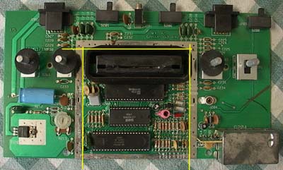
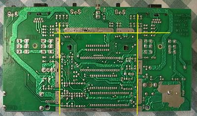
All slices are just inside the metal square, except for the bottom part of the metal square which is left intact.
Now, you can use a band saw if you want, but it's actually almost easier (and we don't all have band saws) to use a utility knife and SCRAPE the PCB along the cut-lines. Scrape along each cut-line on both sides two or three times deeply and with lots of pressure. You can then bend the board and it should snap cleanly along those lines, much like scoring glass.
NOTE: Even though it may seem easier to pull the knife TOWARDS you as you do this, try moving the knife OUTWARD instead. I cannot be responsible for any injury if you don't handle the knife properly, and besides, if you gash yourself and go to the hospital BEFORE you finish your portable Atari, what are you gonna do while waiting in the emergency room?
OK, so now your board looks like this:
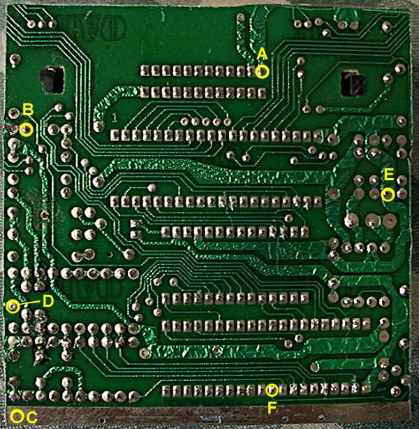
In this current state it won't work, you need to jump a few connections first (much like gaining success in the music industry)
The secret fact of life is most everything in the universe seems to run off 5 volts (even the Sun!) The 2600 is no exception. You'll need to apply the +5 volt current to spot "E" and also to spot "D".
It's good to keep your feet on the ground so the unit must be re-grounded. The metal stuff at the bottom "C" is all ground, so connect your battery ground to that. Then, connect this metal "ground bar" "C" to spot "B", and connect spot "B" to spot "A".
Congratulations, the Atari will now run!
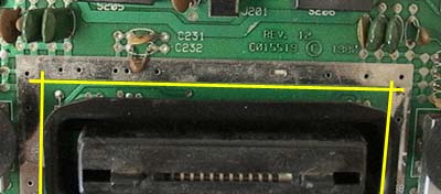
BUT, it's not enough. You need to attach a potentiometer that deals with the color of the unit. On your castaway Tom Hanks-esque boards, you should see this thing:

Desolder that sucker and pull it out. You'll need to reconnect it to the board.
Connect "A" on the potentiometer to spot "F" on the Atari board. Connect "B" to the Atari's ground. Finally, connect "C" to the UNREGULATED positive power supply.
Typically you'll have a power supply with 7-9 volts coming out of it, such as a rechargeable battery or a wall adapter. The Atari only requires 5 volts, so you use a linear regulator to drop the voltage to 5 volts. This is usually done with a 7805 linear regulator, which turns the excess voltage into heat.
For the color to be correct on an Atari, the UNREGULATED power (again, typically 7-9 volts) is applied into spot "C" of the potentiometer pictured above. Sorry for the excess verbiage but I wanted to make it clear.
Ok! That should do it. You can now connect joysticks and what not as described in the other "How To" sections. OR! You can use this sliced-up board to build a Rev 5 once I post the files and specs for that unit.
Have fun!
