- Atari 2600 Composite
Video Mod: Reloaded -
Recently I fixed up what I thought was a long-dead Atari 2600. I then decided to come up with a better composite video mod then the one I've been using for over 4 years. After a few hours of tinkering I did! It's similar to the normal mod (found on the www.benheck.com site and in my book) but gives a cleaner signal with no interference from the audio and seems to be more compatible with more TV's. I tested it with A LOT of my games and compared it to emulated ROMS on my computer for higher accuracy overall. Anyway, here you go:
1) First check what type of Atari 2600 board you have. Though they are usually very similar, some have traces coming from the TIA chip go to different places than others. Check the back of the Atari board (after it's become a square) and look at the lower left corner:
Type A
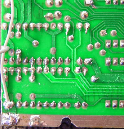
Note the 4 traces coming from the TIA (highlighted) spread out somewhat.
Type B (With audio spot indicated)
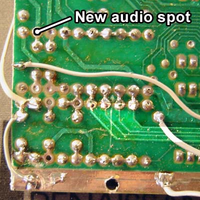
Here the 4 traces (again, as you can see, highlighted!) go to a row of resistors. (Along with a new spot from which to get audio, more on that in a bit)
2) Next, snip/de-solder/crush/ somehow remove the resistors and diodes shown below, depending on what type of board you have:
Type A
You can see 4 resistors and 1 diode have been snipped and pull away.
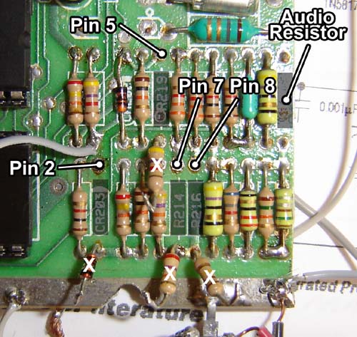
Type B
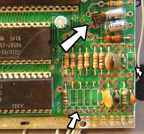
For Type B the same audio resistor is removed (rightmost arrow) but then the lower row of resistors (now an empty space in my photo) are removed.
For both types of mods it
may also be necessary to snip the center pole of the audio transistor
(large upper arrow in "Type B" photo above) and then get the
audio signal from the spot marked "New audio spot" on the
first
Type B photo.
Originally these resistors are connected to the 4 spots on the Stella chip (TIA) that sends out the video signal, then they mush it all together along with audio to send to the (now removed) Atari RF box. By removing these resistors we isolate the signals coming off the TIA chip to keep it cleaner.
NOTE: In my book the Master Lead List for the Atari 2600 uses letters instead of pin numbers. Here are the equivalents:
TIA Pin 2: U
TIA Pin 5: T
TIA Pin 7: S
TIA Pin 8: R
3) Ok, with those things removed it's time to replace them with new resistors! For some odd reason (probably related to the ozone layer or electronics) you can't use the same value resistors for this next part as the ones you removed. [shrug]
Make this circuit as shown below:
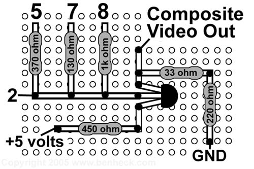
3) TIA pins 2, 5 7 and 8 connect to the spots shown. Potentiometers are not used though you can if you wish. I determined these values by using potentiometers to tweak the signal and then checking what resistance they were at.
4) Some of these resistors are uncommon values. You can "make" these resistors by wiring other resistors in series to get as close to the desired value as possible. For example, I made a 450 ohm resistor by connecting two 220 ohm resistors and a 10 ohm resistor in series (one right after the other, like how batteries are placed into a device)
5) The black thing with 3 legs is a transistor. The type shown is a 2N4401 NPN transistor, it's Radio Shack part #276-2058. This is pretty similar to the NES video boost circuit in my book except a) more resistance on the 5 volts coming in and b) the composite video signal is picked up in front of the 33 ohm resistor, rather than after it.
And that's it! So simple even I can do it! Remember you'll still need to hook up the Atari 2600's color delay potentiometer, which basically lets you set the picture's tint (but without it you're in black & white land). Rewiring that thing is covered in my book.
NOTE: To use this video output mod with a 5" PSone screen use these different resistors as indicated:
![]() 377 ohm resistor instead of 370 ohm
377 ohm resistor instead of 370 ohm
![]() 193 ohm instead of 130 ohm
193 ohm instead of 130 ohm
![]() 680 ohm instead of 1K
680 ohm instead of 1K
The rest of the circuit remains the same.
Some final notes:
1) This mod was done for Atari 2600's that have been hacked into 4" x 4" squares (as I so love to do) If you're modding an entire Atari 2600 you should remove the RF modulator *big silver box on lower right of board) before doing this mod. This keeps it from "recombining" the video signal you're trying to separate.
2) For info on hacking your Atari 2600 into a 4" x 4" square check out my book (plug plug!) or hit the How To pages.
3) This particular how-to also shows one way to get the audio signal, which is really simple and covered in my book and the aforementioned how to pages. Just wanted to mention it.
4) To adjust the video signal you can vary the types of resistors you use (the ohms) From what I saw using too low of values "overloaded" the signal and either scrambled it (when using too low of resistors for the TIA pins) or washed it out to black and white (when using a lot less than 450 ohms for the +5 volts in)
5) When using this mod with a PSone screen, you can bypass the 450 ohm resistor between +5 volts and the transistor to brighten the image and increase contrast. You will loose some edge detail though. (You can always try varying the resistance instead of straight bypass of the 450 ohm resistor) For regular TV's it's best to leave the 450 ohm resistor as is
6) If you've done this mod and it works (or doesn't work) then let me know! (I guess I'm soliciting a response either way...) I can only test so many different TV types so I'm curious what is compatible. If I get enough responses I could list [compatibilities] on this page. This new mod IS compatible with Sony Vegas, for example, whereas the old mod wasn't.