genesis 1 board with pic (big)

Includes but not limited to: SNES, Genesis, Sega CD, PlayStation 1, Nintendo 64, Dreamcast, Game Gear and I guess the Virtual Boy.

Moderator: Moderators

phantom92opera
Posts: 260
Joined: Tue Dec 26, 2006 11:07 pm

Post by phantom92opera »

hey folks. its phantom here with some updates! ive cut the board down to a reasonable size and removed some unnecessary parts!
ive also bent plenty of caps to make space and am debating whether or not to move the cart slot.
i have power incoming thru the power supply of my psone screen (+5v) and hardwired the power switch to "always on" and i got rid of the 7805's and just wired the input to the output on both. this gives me a voltage a little under 5 because the power goes thru multiple capacitators on its way to these 7805's.

i am curious as to the use of those capacitators (change a/c to d/c voltage?? there for resistance) and if they are removeable. i don't want to fry the board so i am probably not going to try to remove them or bypass them. by checking multiple traces, i have discovered that the powersupply passes thru a few diodes as well, and i am considering just putting the power into replacement diodes then straight into the 7805 output instead. if its a steady 5 foward voltage, there should be no problem with frying the board as all other parts are intact. example below
Image
This however skips the powerswitch, which doesnt matter anyway cuz ive already bypassed it!
i will continue to update and fill you guys in! i have yet to pick up my signal boosting parts for my rgb and csync amps but when i have em. you'll see em!
stay tuned!


in hopes for a good portable
-the phantom

PS one more question for the electronics gurus lookin. above the controller ports (base right of board) there are a bunch of squares labelled EM then a number. what is this part or what does EM stand for that matter. this is semi important because i removed the external port above (not ever gonna use it.) and a set of those lies directly below that port (all traces connect from an IC (the motorola main IC) and then to the EXT port.) they are removed in the picture i found online and have been using to show you all my progress. sorry but i cant take any of my own pictures because my camera sucks
sam_thornley
Posts: 137
Joined: Sat Mar 10, 2007 7:32 pm
Location: Derbyshire, UK
Contact:

Post by sam_thornley »

So are you running the whole directly off 5v from a battery? Just relocate the regulators because if you are going to use a psone screen it requires 7.2-8v. Then the whole system can run off a 7.2v battery, so you have'nt got two separate volatges around the system. If you take 5v from the psone screens's 7805's and power a full genesis board won't they over heat and keep shutting down because of higher current draw and thermal protection?

In my nearly finished master system portable i'm running the master system 2 board and psone screen off 7.2v, leaving the master system's 7805 intact to supply +5v to the chips.
phantom92opera
Posts: 260
Joined: Tue Dec 26, 2006 11:07 pm

Post by phantom92opera »

i currently finished the video circuit and am running ahead of schedule.
i am running the console off of the +5v from the screen, which will run off of a 7.2v-7.5v battery. the power comes from pin 12 of connector 1 on the screen. alternative 2 is to run both of them off of the battery and to ensure a steady voltage, i will replace the regulator (7805)

today i will try to pick up supplies to make the controls (10k resistors and i already have tact switches.. out of pcb tho.)

will a 7.2 ni-cd battery power the screen or must it be 7.5?
thanks for the advice
-phantom
sam_thornley
Posts: 137
Joined: Sat Mar 10, 2007 7:32 pm
Location: Derbyshire, UK
Contact:

Post by sam_thornley »

The psone screen will run fine off 7.2v even though it is rated at 7.5v. A 7.2v ni-cad will do fine, though i recomend at least 800mAh for a decent play time if your using an led modded screen.

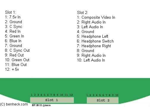
Pin 12 on the psone screen is a 5v input. It enables RGB mode when a +5v source is connected. By default the screen waits for a composite input. To get 5v from the psone screen you will have to take it off one of its 7805's directly.
phantom92opera
Posts: 260
Joined: Tue Dec 26, 2006 11:07 pm

Post by phantom92opera »

yep, i have the 12th connected to the 7805 on the back where i got power for my leds. Controllers will be tomorrows project, as I will be working and mowing the lawn tonight and tomorrow morning! thanks for all the views and hopefully this project will turn out as i envision it!

PS ! i just picked up a cart at sal val for testing and i will have results tommorow morning. the diodes i took from the board and wired to the 5v wires didnt do justice and slowed the 5v to about 4.3-4.5v so i am going to remove them and wire the +5 to the console without the diodes (this shouldnt affect much as i have current flowing one direction only... right?). if this doesnt deliver a constant 5 (voltage drop thru long wires) then i will go back to a 7805 and tapping 7.2 from a battery.

thanks again for looking!
phantom
lovablechevy
Portablizer Extraordinaire
Posts: 1104
Joined: Wed Nov 01, 2006 3:09 pm
Location: busy with a project
Contact:

Post by lovablechevy »

i'm so glad that you are working away at this! can't wait to see some progress pics! :D
they call me the Queen of Bondo, though maybe i should be called the Queen of Epoxy Putty

Image

current project - code name: blue mushroom!
phantom92opera
Posts: 260
Joined: Tue Dec 26, 2006 11:07 pm

Post by phantom92opera »

haha no camera :x
i have a cam fone and i could upload my current setup. its quite wire-y if thats a word but thanks for all your support! your the one who helped me want to pursue this. that 1st guy was so negative lol. anyway. i'll post 2moro afternoon!
lovablechevy
Portablizer Extraordinaire
Posts: 1104
Joined: Wed Nov 01, 2006 3:09 pm
Location: busy with a project
Contact:

Post by lovablechevy »

camera phone would be ok. we just like any pics we can possibly get! well, at least i do... guess i won't try to speak for everyone here.

and you're right, he was being very negative. glad i could help you decide to do it!
they call me the Queen of Bondo, though maybe i should be called the Queen of Epoxy Putty

Image

current project - code name: blue mushroom!
phantom92opera
Posts: 260
Joined: Tue Dec 26, 2006 11:07 pm

Post by phantom92opera »

hey folks, here are some camera phone pics of my setup thus far! i have amped rgb signals that look be-a-utiful. i do however have a problem. neither speakers are working or getting signals. i have wires 2 and 9 going to the right signal (pin 2 on stereo plug at bottom right corner of genesis board) and pins 3 and 10 going to pin 3 (same spot just 1 over). also, 4 and 8 are wired to the ground for this plug. the video works fine and the volume is up as high as possible however the system outputs no sound

after some tests, i found that the ground wires for both speaker ports were breaking the circuit. with the red prong from my multimeter on the positive lead, and the negative on the negative lead, no current flowed.
however when the positive prong was on the pos lead and the negative on any other ground spot i got a flow going. how may i correct this problem to get sound from my screen?

Image
Image
Image
Image
Image
Image
Image


EDIT: I have found a solution and will try tommorow morning. http://www.retroleum.co.uk/psone_lcd.html i need to wire "headphone switch" (Pin 6 connector 2) to ground to work the speakers. on top of that i only need pins 9 and 10 connected because they are the audio in for rgb mode, whereas composite requires pins 3 and 2.
lovablechevy
Portablizer Extraordinaire
Posts: 1104
Joined: Wed Nov 01, 2006 3:09 pm
Location: busy with a project
Contact:

Post by lovablechevy »

oh good, you found that. i was just about to give you the solution to your sound problem! :wink:

looking good so far! thanks for the pics!
they call me the Queen of Bondo, though maybe i should be called the Queen of Epoxy Putty

Image

current project - code name: blue mushroom!
phantom92opera
Posts: 260
Joined: Tue Dec 26, 2006 11:07 pm

Post by phantom92opera »

audio is functional but seems staticky. any way to improve audio (amplifier or quality enhancing circuit?) please let me know. im looking at this circuit but wondering if its worth the case space... http://www.techlib.com/electronics/audi ... transistor

aside from that the controller is 3/4 done. all tact switches soldered. and some connected to the ic but no mobo connections just yet. i wanna fix vid and audio first. on top of that i have to plan a hand built case! i will measure dimensions and update soon!

UPDATE: grrr! hand wired controller isnt working. its made in 2 parts 1 pcb for dpad and 1 for abc and start. i wired the pins and whatnot to the board and the game seems to run as if one button is constantly being pushed. i have determined that button to be "a" i think. all of my traces and wiring is correct i went over it 3 times. perhaps the cart is defected. i will reinspect after work tonight!

-phantom
sam_thornley
Posts: 137
Joined: Sat Mar 10, 2007 7:32 pm
Location: Derbyshire, UK
Contact:

Post by sam_thornley »

All looking good so far :D

One thing i noticed though, did you remove the CFL inverter off the top of the psone screen or did you just wrap tape around it? If you've left it on its still sucking a fair bit of power. Its stafe to remove the transformer to "Kill" the inverter circuit.
phantom92opera
Posts: 260
Joined: Tue Dec 26, 2006 11:07 pm

Post by phantom92opera »

yea i have it there and i went to remove it but i had already soldered and screwed everything down and didnt know if it was worth the risk of breaking a connection, i taped over the semi cut traces i made. i guess i can try to remove it again. im using a box knife and wire cutters haha. i guess i'll just really have to make the grooves deep b4 i try to cut because then the crack wont run into the rest of the board.

all of my tact switches were taken from other devices (vcrs cd drives etc) therefore i think one or two are shorted and are automatically on. i will try removing buttons one by one to figure out which ones are broken. if this is not the case, then i mustve wired the ic to the console wrong, which i will check second.

thanks for all your support
phantom

PS i wont be back from work till after 5 so dont expect a post till 630-7ish!
and one last question... in the amp i built earlier for my rgb on my genesis (on the bottom) there are 2 lines Lch and Rch are those audio? (left channel/right channel) if so I will attempt that circuit in hopes of better audio quality. my final question (still related - bear with me) is will the 10uF capacitator go onto the R and L signals into the screen, or on the speakers wires???

sorry to keep you reading - phantom
phantom92opera
Posts: 260
Joined: Tue Dec 26, 2006 11:07 pm

Post by phantom92opera »

hey guys!
hope everyone enjoyed fathers day (for those it applies to)
anyway a quick update is that the i think i overworked and fried the IC i was using for the controller as im no longer getting a signal. it was surface mount and maybe my connections werent strong enough but i opened my second controller to find a much larger version and will use that later this week.

hope to post soon!
phantom

THANKS FOR OVER 1K LOOKS!
phantom92opera
Posts: 260
Joined: Tue Dec 26, 2006 11:07 pm

Post by phantom92opera »

hiya guys, did some work this morning and used a better chip for the controller, all the wiring is perfect and im still having some malfunctions.

i have determined the error to be the tact switches
they are assorted and removed from vcrs, cd players, etc and must have been shorted crushed or whatever after desoldering.

i will just order a bunch from digi key and after that if it doesnt work. i'll consult the IC again.

aside from that i will still have to design a case and possibly relocate the cart slot
Post Reply