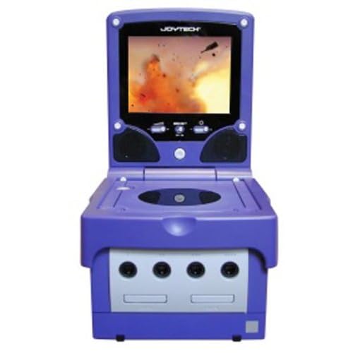
Joytech 5.6 tft GC Monitor for use with Snesp help

If you're making a portable you probably need something to watch it on. (Unless you want to guess what's happening in the game, but I wouldn't advise that) Anyway, this forum is your "Hacking a pocket TV/screen" one-stop solution. Share your experiences and knowledge here.

Moderator: Moderators

sdh
Posts: 175
Joined: Tue Apr 24, 2007 8:19 am
Location: Stockholm, Sweden
Contact:

Joytech 5.6 tft GC Monitor for use with Snesp help

Post by sdh »

Hi all!

Image
http://www.amazon.co.uk/Joytech-GameCub ... B00006FRKX

I just bought a screen like this and thought I'd ask if anyone here has used one of these before and has any useful info
about it before I get started? I'm wondering if I'm able to pull anything of the board to save space? For example there's
this big component beside the bulb power output which I figured was specifically used for it somehow.
The screen is kind of fatty (almost 2cm on thickest part) so it would be good news if something could be stripped.
And is there any pinouts for this floating around, like which pins I can use to hook up the video/audio where to snatch power for led?

I can post pics of the boards later if needed, I'm @ work right now.
sdh
Posts: 175
Joined: Tue Apr 24, 2007 8:19 am
Location: Stockholm, Sweden
Contact:

Post by sdh »

Bump! :o

So, with my Shinju mod done for now I want to get back to my SNESp.
As I live in Sweden I have a hard time finding the recommended screens for this mod, so I'm stuck with this Joytech 5.6" tft for GC.
I've understood it is of very good quality which is nice, while having basically zero info in the forums of this specific model is not.

I have all the guts before me, but I can't find the power regulator as shown in the portable screen hacking guide at ExtremeTech.
My guess is that regulator in this model is the one labeled Z200-TP-0050J (2nd image), but that's where I need some help to be sure.

If anyone has modded this type of screen before I would appreciate what ever info you can provide to help.
If anything on the board can be discarded to preserve space for example.

1. Overview of all parts
ImageImage

2. Board 1, close up
Image

3. Board 2, close up
ImageImage

4. Board 2, backside close up
ImageImage

5. Board 3, close up
ImageImage
sdh
Posts: 175
Joined: Tue Apr 24, 2007 8:19 am
Location: Stockholm, Sweden
Contact:

Post by sdh »

:(
I'm sorry to bump this again but I would really appreciate if someone that has good experience with screens could take a look at the boards and give me some pointers on how to proceed with this. The main goal right now is just to led mod it and hook it up to the snes. With 562 views at least 1 skilled person must have dropped by, right? So if this 1 person also don't know what to do I'm at least aware that this screen too hard for me to mod. Then I will try get hold of one that is well documented.
Mario
Posts: 1383
Joined: Mon Mar 05, 2007 7:20 pm
Location: Sunny California

Post by Mario »

I just saw this topic. The screen had some plug that fitted onto the Gamecube, right? You just have to find a pinout of the GC's video plug.
Tibia
Posts: 1319
Joined: Thu Feb 28, 2008 2:02 pm
PSN Username: Tibia1013
Steam ID: Mulder101361
Location: Istanbul, not Constantinople
Contact:

Post by Tibia »

The GC and the SNES use the same video plug.

Where on the board does the GC connect to the screen? I see a composite out cord, but I don't see where the input is located.
This post brought to you by David Duchovny's glorious nipples.
sdh
Posts: 175
Joined: Tue Apr 24, 2007 8:19 am
Location: Stockholm, Sweden
Contact:

Post by sdh »

Mario wrote:I just saw this topic. The screen had some plug that fitted onto the Gamecube, right? You just have to find a pinout of the GC's video plug.
Found the pinout.
Though I'm not sure the wire colors are correct, and do they usually have resistors and capacitators?

Image


Tibia wrote:Where on the board does the GC (snes?) connect to the screen? I see a composite out cord, but I don't see where the input is located.
This is what you meant, right?

Image
Tibia
Posts: 1319
Joined: Thu Feb 28, 2008 2:02 pm
PSN Username: Tibia1013
Steam ID: Mulder101361
Location: Istanbul, not Constantinople
Contact:

Post by Tibia »

Yeah. Is that where the console would be attached to the screen? And did you already cut off that connector?
This post brought to you by David Duchovny's glorious nipples.
Mario
Posts: 1383
Joined: Mon Mar 05, 2007 7:20 pm
Location: Sunny California

Post by Mario »

Like Tibia asked, did you already cut the connector? This screen might have a non-standard pinout, so the wire colors probably won't match. You would have to use a multimeter on the connector to find what wires go to what.
sdh
Posts: 175
Joined: Tue Apr 24, 2007 8:19 am
Location: Stockholm, Sweden
Contact:

Post by sdh »

Yeah I have already taken the multi out connector off, shouldn't I have done that yet? (oops) :P So the wires you see are the ones that's going to lead into the console. I have a multimeter here and can test the wires but how will I know which is which based on the outcome?
Mario
Posts: 1383
Joined: Mon Mar 05, 2007 7:20 pm
Location: Sunny California

Post by Mario »

Well, seeing as how you've already taken off the connector, there's not much you can do but guess. :) Are you using composite? Attach the ground of composite to any ground spot on the board, and touch the signal wire to each of the pins (except ground) and see which one shows a picture.
sdh
Posts: 175
Joined: Tue Apr 24, 2007 8:19 am
Location: Stockholm, Sweden
Contact:

Post by sdh »

Thanks, will try that!
So, for the led mod I just need to point around with the multimeter til' I find some lower voltage, like +5? (Then hook em up with a resistor of course)
Mario
Posts: 1383
Joined: Mon Mar 05, 2007 7:20 pm
Location: Sunny California

Post by Mario »

sdh wrote:Thanks, will try that!
So, for the led mod I just need to point around with the multimeter til' I find some lower voltage, like +5? (Then hook em up with a resistor of course)
Well, I don't see a 7805 on your board, so "poking around" probably won't help. What voltage does the screen run off of? Use ledcalc.com to figure out what resistor to use for the LEDs.
Tibia
Posts: 1319
Joined: Thu Feb 28, 2008 2:02 pm
PSN Username: Tibia1013
Steam ID: Mulder101361
Location: Istanbul, not Constantinople
Contact:

Post by Tibia »

If you end up keeping the board with the power LED on it, you could run from there.

Otherwise, if your multimeter reads DC voltage, and most of them should, you ought to be able to find some component running 5v to tap into. The 7805's just easy to identify. It's not the only thing putting out 5v.
This post brought to you by David Duchovny's glorious nipples.
sdh
Posts: 175
Joined: Tue Apr 24, 2007 8:19 am
Location: Stockholm, Sweden
Contact:

Post by sdh »

Mario wrote:Well, I don't see a 7805 on your board, so "poking around" probably won't help. What voltage does the screen run off of? Use ledcalc.com to figure out what resistor to use for the LEDs.
It uses the Gamecube power adapter with an 'pass-by-connector' for power and the adapter says 12V. Is this a problem since the SNES uses 9.8V?
Tibia wrote:If you end up keeping the board with the power LED on it, you could run from there.

Otherwise, if your multimeter reads DC voltage, and most of them should, you ought to be able to find some component running 5v to tap into. The 7805's just easy to identify. It's not the only thing putting out 5v.
Yeah I'll be keeping it since it has the volume, brightness and SRS controls. So I'll check if I can find 5V somewhere tomorrow.
Tibia
Posts: 1319
Joined: Thu Feb 28, 2008 2:02 pm
PSN Username: Tibia1013
Steam ID: Mulder101361
Location: Istanbul, not Constantinople
Contact:

Post by Tibia »

Well, if you go where the existing LED is, you shouldn't need any resistors. I'm just not sure how many you'd be able to run off it.
This post brought to you by David Duchovny's glorious nipples.
Post Reply