Do you have a technical question that doesn't really fit a specific console? Want some general info on electronics, hacking, making cookies, etc? Here's the place to ask! Go nuts.
I started designing a template sheet to make subminiature connectors and noticed that in the reference libray I was using, components with more than three rows of pins have thir grids offset from 0,0 by between 0.1 mm and 2 mm. I do not know if this is because of my reference library having been distorted (many other components are offset by varying degrees, and angles) or deliberate design.
I won't do the research to find the correct measurements if no one anticipates needing a sub-subminiature connector outside of the common 9,15,25,37 dimensions.
docs.google.com2011.04.05.pdf contains the first four (most common) types for use as a drillling template. Dimensions are described below.
Rough sizes, not definitive.
(dimensions are described in inches for consistency, though some components are drawn in mm)
pins    9      15     25^    37     50^    78*

Thread  0.493  0.656  0.926  1.25   1.203  1.202756
        0.0    0.0    0.0    0.0    0.0    0.0
Drill   0.13   0.13   0.13   0.13   0.13   0.11811

Shell   0.275  0.44   0.71   1.035  0.958  0.981339
        0.102  0.102  0.102  0.102  0.158  0.164992
Shell   0.245  0.41   0.68   1.005  0.988  0.951339
        0.102  0.102  0.102  0.102  0.158  0.164992
radius  0.053  0.053  0.053  0.053  0.053  0.053

Pin     0.027  0.027  0.027166667
        x      x      x      0.027166667
        x      x      x      x      0.02715625
        x      x      x      x      x      not calculated
        0.056  0.056  0.056  0.056  0.112  0.122835
        --     --     --     --     --     0.040945
Drill   0.04   0.04   0.04   0.04   0.04   0.035433

^ is distorted/ some dimensions are not symmetrical same relative to the 0,0 cordinate, original pin spacing may be inconsistent but preserved. There is a pin at x,0.
* is clearly asymettrical, did not bother to calculate the pin layout for this one.
Progress!
I now know that the eagle dimensions are off of spec by 0.05 mm (not that I care enough to correct that).
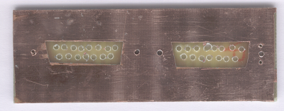
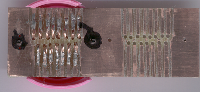
Tried only taping the areas to be preserved.
Residue from repositioning tape has clearly impeded the etching process.
Holes on left drilled first using only horizontal scoring.
Holes on right drilled using both vertical and horizontal scoring.
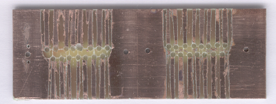
Due to fatigue I used my face to stabilise the drill for the first few holes then noted that bit had developed an enctricity that made keeping it from wanderingquite difficult.
Tried using double scoring instead of my face in the middle.
For the last five another bit was used for an awl, and I resumed using my face to brace the hand drill-machine.
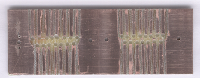
Tried to tape the entire surface then cut awat the mask as needed.
Residue not succesfully scraped away has clearly impeded the etching process, fortunately I planned for this.
A quick visit with the hacksaw and the traces are seperated.
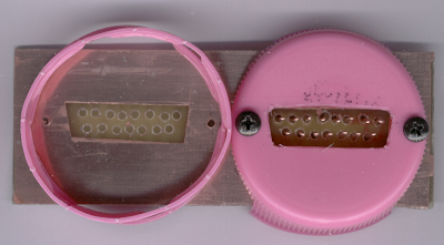
A pink (for breastcancer research) plastic cap was cut to meet the connector shell and screwed in place.
The fit is perfect.
Picture taken after half an hour of playing with testing it.
I ranout of 19 AWG wire and didn't realise it. Just as well, without a drill press the holes aren't aligned well enough to use that anyways.
Hooks were formed from of 26 AWG (oxygen free) and soldered into the holes. Their flexability should compensate for the misalignment.
Strain reliefs were formed, and the hooks soldered into place.
The 'copper' colour on the solder is copper. Discovered earlier that polishing with aluminum-oxide deposits a layer of copper on the solder.
Sealed screws and parts of some pins when my arm started to slip.
New question:
Using aluminum to deposit copper on tin, lead and silver... It doesn' t sound like a good idea but what consequences fo this might I expect?